Coaxial Termination refers to the process of joining the end of a coaxial cable with a resistor to stop signal reflection, usually ascribed to a 75 ohm resistor.
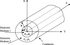
Structure of the Coaxial Cable
The Conductive Core The main element is the inner conductor of the coaxial cable. Typically, these are copper or a less expensive copper alloy. It is responsible for transmitting electrical signals and has a certain diameter, depending on the purpose and requirements for signal magnitude. The maximum varies from 0.5mm to 2.5mm. It is perfectly calibrated, as evidenced by extraneous resistance, well-controlled by the signal over long distances.

An Insulating Layer It surrounds the inner conductor and prevents electrical leakage and short circuits. There are such types of materials for manufacturing it as polyethylene, foamed polyethylene, and other polymers with good dielectric properties. Its thickness is varied, but, as a rule, does not exceed 0.3mm-0.5mm. This type of insulation is not only a guarantee of the proper functioning of the cables, but also of safety, as it does not allow the inner conductor to come into contact with objects located outside the cable and not transmitting a signal.
Shielding Braid This is essentially a metallic mesh that surrounds the insulation. This cladding is necessary for shielding between the inner conductor and the insulation. In other words, the transmission of data is impeded by exterior frequency signals. The best braid to date is one made of copper, less often – aluminum, and even less often – a combination of both metals. It is usually of such high quality that the percentage of proper shielding, which is achieved by a braid, reaches 95% and sometimes more.
Outer Jacket of Coaxial Cable First of all, the outer jacket is the protective sheath surrounding the entire coaxial cable setup. It is constructed from durable material such as PVC or Polyethylene, making it rugged to endure harsh environmental conditions, including UV exposure, temperature extremes, and rough physical treatment. Second, the outer jacket is about 0.6mm to 1.2mm thick. This thickness offers adequate protection without making the coaxial cable bulkier. Third, this layer does not turn the cable into a rigid tube. It is somewhat flexible, allowing a person to route it easily through narrow spaces without losing its shape or sustaining damage from sharp objects, for example.
Function of Termination: Signal Integrity In the first place, termination marks the end of the coaxial cable setup. Second, it is an optimal way to keep signal integrity. If not properly terminated, the signals would not have a defined pathway, and most of the energy would simply be reflected, progressively weakening the signal strength as it propagates along the only path available. Reflection is the main cause of signal loss. It fortunately can be dramatically reduced. When the termination is just right, its impedance is the same as the characteristic impedance. Many video and data transmission cables, for example, have a characteristic impedance of 75 ohms. In this case, the termination would have no more than 0. The reflection losses, which are a signal of signal deterioration, are equal to 4.8*10^-4. In other words, the signal is near perfect. It is very strong and free of distortions that can be attributed to reflection.
Impedance Matching Impedance matching means that the termination offers the same resistance as the coaxial cable. It is important, for example, when a signal is transmitted from a source through a cable. When the impedance is mismatched, the portion of the signal not transmitted is reflected to its source, which can potentially damage it if the signal is very strong and the source is very weak. With quality connections, impedance can be adjusted. The best one even meets the least 1% factor.
Noise Reduction In the context of coaxial cable systems, noise can either refer to electromagnetic interference from other devices within the vicinity or radio frequency interference which may come from the immediate environment. Noise reduction is significantly improved through termination coming out as a less susceptible and stabilized signal. Grounding the termination properly also offers another avenue of eliminating noise from the cable in question. The termination process reduces noise-induced signal loss as lows as 90%, leaving a clear signal.

Types of Coax Terminations
Resistive Terminations These terminations are mere devices for the consumption of the signals’ energy and are positioned at the end of the coaxial cable. The end in question is where the signal bounces back due to lack of an output apparatus or device. These resistive terminations are majorly used when the device on the end is not in operation anymore. In a common example in a cable TV system, the end of the cable is the point at which the resistor would be placed. Resistive terminators have a varied impedance of approximately 50 ohms that corresponds with the coaxial cable’s impedance.
Reactive Terminations Reactive terminations, on the other hand, are intended for use in applications where the signal must be terminated at a point that is not actually the end of the cable run. Using a combination of capacitors and inductors, these types of terminations can present a short or open circuit to the signal across a wide range of frequencies. Reactive terminations are commonly used in high-frequency or RF applications in order to terminate the signal at one specific frequency while passing the signal through at another. For example, a reactive termination might be used in a television broadcasting system to terminate the signal at the transmitter, and yet still allow the signal to propagate down the line and on to the television’s broadcast antenna.
High-Pass and Low-Pass Filters High-pass and low-pass filters are another specialized type of termination that allows only specific frequencies to pass while blocking the rest. A high-pass filter will pass frequencies above a certain cutoff while attenuating those below, useful in many applications to eliminate low-frequency noise or interference. Similarly, a low-pass filter lets frequencies pass that are below a certain cutoff but will not allow higher frequencies to pass. These filters can be used in conjunction with either resistive or reactive terminations to offer a more complete signal termination solution as well as providing a means of blocking any extraneous noise. For example, a low-pass filter could be used in the cable TV system to ensure that only the video signal frequencies pass to the viewer’s TV set, blocking any out-of-band interference that could contribute to snow in the picture.

Termination in Cable Television Systems Termination is used in cable television systems to deliver a clear and uninterrupted signal to viewers. Cable TV networks are typically designed as a tree and branch architecture, where the signal comes from a headend, then to a set of nodes, and from there to the subscribers. Proper termination is essential for minimal signal loss and reflections impacting the picture of the provider and eventual service interruptions. In this case, the termination matched to 75 ohms is an industry standard to guarantee quality and performance of the entire coaxial cable network. The repeater used for signal strength restoration is connected through a terminator, which prevents signal returning from the terminating end and multiple reflections from other receivers connected to the same cable. Such a strong connection maintains the termination network under optimal conditions to ensure that the repeater in the entire network powers adequately.
Termination in Telecommunication Networks In telecommunication networks, coaxial cables are used for internet, telephone, and other services. Such networks are susceptible to a return loss of up to 0.3 dB, proved by calculation of a 1% impedance mismatch. In telecommunication networks, use of terminators is necessary for maintenance of the 50-ohm impedance tendered by telecommunications cables to ensure that the data transmission stays optimal.
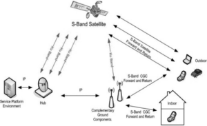
Satellite TV and Radio Satellite TV and radio systems require proper termination to make sure that the signals received from satellites are the best. The terminations in this case should meet particular requirements, such as high operation frequencies. The frequency range for the signals of satellite TV, for instance, varies from 950 MHz to 2150 MHz. The terminators, in this case, should be effective for most of these frequencies to provide a good signal reception. If satellite terminations are poor, a satellite dish may lose 50% of the signal, which is a significant threat to TV picture and sound quality or signal clarity in the case of radio. In many cases, terminations for the satellite should be equipped with Low Noise Block Converters to reduce the level of interacted noise in the signal.
Installation and Maintenance
Connector Types and Choices The selection of the right connector type is crucial for the correct installation and maintenance of the coaxial cable systems. Three types of connectors, such as BNC, F-Type, and N-Type connectors, can be distinguished. The main applications and specifications for each type of connectors are as follows:
- BNC connectors are popular with test equipment, and they are documented for their quick-disconnect operation.
- F-Type connectors are used for most consumer electronic devices, and every cable or satellite television installation.
- N-Type connectors are often applied to connect WiFi antennas and other radios for extended applications over 500 MHz.
The selection of a connector type should depend on the frequency limit, signal strength, and whether a cable is for indoor or outdoor use.
Best Practices for Termination To achieve the maximum efficiency of any coaxial cable system, it is necessary to consider best practices for termination. It is important that the impedance of the terminator matches the characteristic impedance of the cable to avoid signal reflection and degradation of the transported signal. The installation of terminators should be done using appropriate support equipment to ensure the process is precise and complies with the manufacturer’s recommendations. Periodic inspections of connectors for signs of damage or corrosion are also recommended, as they can lead to signal loss or individual connections dropping out. In high-traffic areas, using strain relief and securing devices can extend the life of the connection and limit the need for regular maintenance.
Troubleshooting Coaxial Cable Connections
When troubleshooting coaxial cable connections, the first recommendation is to carefully inspect the points of connection. The most common cause of signal loss in coaxial cables is poorly fitted or corroded connectors – re-seating or cleaning them can resolve the problem. If there is no change in signal strength after such maintenance, then the problem might be with the cable itself, or with the terminator for the cable. It is possible to determine this through testing the signal for strength and quality, with any loss exceeding 3-5% being indicative of the termination failing to maximize the cable’s performance. In such cases, the terminator should be replaced with a new one, or re-impedance matched to the specifications of the cable. Regular scheduled maintenance and inspection will prevent small problems from growing into critical failures.


