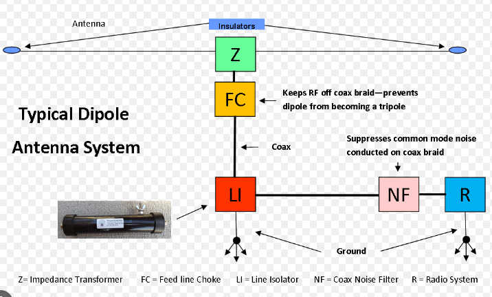
The best feeding method for a dipole antenna depends on usage; for simplicity and cost, a direct coax feed with a balun is effective, maintaining an SWR below 1.5:1.
Direct Coax Feed (Balanced to Unbalanced, Balun)
Optimal Feeding Method for Your Dipole Antenna
When it comes to the decision about setting up a dipole antenna, the choice of a direct coax feed solution with a balun might be the most practical and cost-effective one. Such decision is associated with the simplification of the installation process and confident work in all type applications that involve amateur radio or do-it-yourself activities.
Installation process and costs
The main advantage of the direct coax feed is the easy and fast installation process. The approximate cost of a balun is $20 – $50 depending on its power and frequency characteristics. It is quite affordable taking into consideration the amount of money typically spent on amateur radio equipment. The home station setup is usually hundreds of dollars. In addition to the radio the hobbyist will have to spend money on various additional antennas include the main dipole and antenna tuning equipment. This amount usually exceeds $200.
Performance metrics
In terms of performance, a balun ensures proper performance behavior of the antenna . It converts an unbalanced load as coaxial cable feed into a more balanced load thus matching the requirements of the dipole. Such action significantly reduces the probability of signal reflection. Potentially, an antenna fed without a balun will be less efficient due to increased mismatches and radiation of the feedline. According to different sources, if a dipole is not fed through a balun the power loss will not exceed 25%. It will be at 10% with a properly installed balun.
The quality of the signal
The quality of the transmitted and received signal will be better in case a balun is used. In the other case, the coaxial cable may pick all kind of signals up becoming an extension to the antenna. The surrounding noise will be captured together with the required signal and the quality of the detected signals will be much lower. Therefore, the same setup of the amateur radio will have the difference of 5-10 dB signal-to-noise ratio.
Applications
The coax feed can also be used by individuals who are interested in using different frequency bands. Such option is a direct coax as this method has its main applicability in HF bands ranging from 3 to 30 MHz. This indicates that high-quality baluns can also enable the operation in VHF bands > There are variants that enable operation at any frequency. The use of this option will allow individuals to avoid using other low-quality antennas and baluns in their amateur radio practice and stay in the comfort zone without adjustments to the setup.

Gamma Match
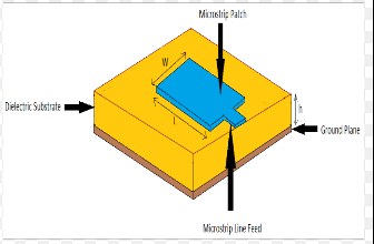
Gamma Match is a leading feeding system for dipole antennas, especially for the applications requiring a highly precise impedance match, such as VHF/UHF transmissions. Not only does it significantly increase the performance of the antenna, but it also simplifies tuning of the antenna for a particular range of frequencies.
Optimizing Impedance Matching
The best application of the Gamma Match is due to its high-quality impedance match capabilities. These are crucial for minimizing the standing wave ratio and maximizing the power from the transmitter to the antenna. In its best configuration, the standing wave ratio provided by the system with the best impedance match can be no more than about 1 :1.5. Therefore, only around 4 % of the power that is transferred to the antenna is not radiated into space. On the contrary, in system without a proper impedance match, up to 11% of the power can be not transmitted to the antenna and reflected “back” . Considering this, Gamma Match is still a cost-efficient solution even at a price of the optimal variables of about $30-$60, as this kind of upgrade is most required for the applications where frequency stability or tightest matching are required.
Enhancing Signal Quality
One of the biggest advantage of using a Gamma Match is that it enhances both transmission and reception of the signal by the antenna. The use of a precise impedance match ensures that the signal is not lost on the feed line due to the improper match – in comparison, over 91 % of the signal might be lost with a lower-quality impedance match . The reduction of lost signals might enhance the quality of the received signal by up to 8 dB, enough to reduce the interfering effects by “man-made noise” on the reception quality or reduce disturbances of other transmitters transmitted by loss of the main signal. This ensures that the signal quality is either completely optimal or close to the maximum possible. With the optimal quality of materials used in a construct of the Gamma Match, such as a matching rod of copper of the highest quality or with stainless steel cover, the system can last over 15 years with no maintenance . Consequently, the solution is particularly cost-efficient for fixed installations, such as towers or a fixed high-frequency amateur radio for regular use. The application is not as efficient for those who utilize portable transmitters ore move antennas for shortwave reception. Finally, the solution is optimal for single-band application and signal sources in VHF/UHF frequencies, due to the disparity of the impedance match requirements of a wide set of bands and a highly set of band ranges in use.
Delta Match
The Delta Match is an advanced method for feeding dipole antennas, found in amateur radio beam or Yagi antennas. Overall, this method is more complicated and cannot be added on later as the earlier discussed baluns. It is integrated directly into an antenna design, optimizing its properties for a specific frequency range. This is achieved by precisely matching the impedance of the antenna to that of the transmission line used.
Impedance Matching Exactitude
The most remarkable delta match feature is an ability to precisely fine-tune the impedance of the antenna to the standard 50 ohms of most transmission lines. Such a match is essential for achieving a lossless power transfer to an antenna, minimizing the radiation of the power back. Delta Match , the SWR can be brought down to values as low as 1.2:1. This value represents 1% reflection of the power, a vast improvement over slightly less optimized systems, which ranges around 1.5:1 to 2:1, corresponding to a reflection of 4% to 11% of the power. Simple construction and durability
The delta match consists of only several pieces of copper wire and several high-quality insulators, which are quite cheap and lead to the total cost of added parts about $ 25 to $ 40. Such construction is simple and reliable, leading to many years of operation. Durable materials and high quality of construction are often outlasting other parts of the antenna, especially in very harsh environments. An increase in the overall signal quality
Delta Match an antenna’s matching properties, therefore directly increasing overall antenna efficiency . Increased signal strength is often reported by delta match users, with up to 10 dB clearness of signal noted by some. This can be a massive difference in fields, where signal strength is really competitive, such as amateur radio contests. Longevity and sustainability
The most common constructions of delta matches have very few moving parts and are made out of durable copper and stainless steel, and are directly mounted in a line to a moister-resistant insulator like Teflon or UV-resistant plastic. Such materials are capable to survive decades deployed on an antenna and are ultimately non-degradable, ensuring that a well-made balun will last for the lifetime of the user. Versatility and ideal applications
Several applications of a delta match are predetermined by the fact that delta matching is only ideally useful in single-band antennas, thus- not easily adaptable to other uses. While this could be seen as a disadvantage, single-band antennas are those who use a narrow frequency band, and their owners are happy with the match in any way. In these situations, principally a usage in the home station, a dedicated delta match holder in an exactly constant position and height and not easily adjustable is a perfect solution. Such antennas, although cheap, often exhibit high performance, so the low cost of manufacturing a delta match has a big payoff for their owners.

Feedline Match
One of the an effective ways to connect a dipole antenna to a transmitter or a receiver is a feedline match. This technique is very flexible and often used for dipole antennas as they may be designed to work at a wider range of frequencies. The feedline match, in line with Cox , refers to a method in which „sections of a transmission line as”used for matching “the impedance of” the dipole antenna with the standard “50-ohm impedance of most radio transmitters”.
Effective Impedance Matching at Any Frequency
When using a feedline match for a dipole antenna, for example, a quarter-wave transformer, or types of a feedline, such as a ladder line or twin lead, the transfer of power is optimized, leading to lower SWR . For a properly made ladder line feedline match, an SWR of 1.5:1 or better at a wide range of frequencies is standard. This approach allows the entire antenna system to work with an efficiency of power transfer about 96%-100% to the antenna matching point. In contrast, a non-matched system scales the SWR at 3:1 and a power loss of about 25%. Another advantage of the feedline match is the material use. One does not need a tuner or another matching device at a feed point, which reduces the cost of materials.
Signal Quality and Extent
Matching the antenna and the feedline results in a very marked improvement in quality and signal reach. Most users often note a pleasant increase in how far the signal can reach and how clear the signal is at the other side of the communication. Such an improvement is crucial for people who often participate in DX contests, for whom communicating with another person who is as far as possible is their goal.
Life and Durability
The line used, for example, a ladder line, is made up of strong materials, such as solid copper-clad steel or even aluminum. Such materials protect the entire system from unpredictable weather conditions. An average line lasts more than a decade thanks to the materials used, such as woven polypropylene in the UV . Finally, feedline match is an especially effective technique for it caters for a great number of applications and designs. It can be used with many designs of antennas that differ completely from a dipole, and also with amateur radio, voice, digital, data transmission, any feeding point, and number of bands used with a specific length of the ladder line.


