Waveguide corners, bends, and twists adjust signal paths in confined spaces. For effective use, bends should have a radius at least 2-3 times the waveguide width (e.g., 45.72 mm for WR-90). Twists maintain signal polarization with minimal loss, typically below 0.15 dB for 90-degree twists.
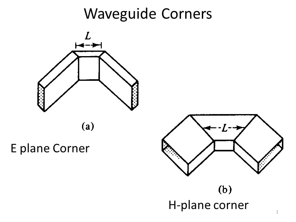
Waveguide corner
Waveguide corners are used to change the direction of signal propagation, and common application scenarios include the need to rewire a signal in a limited space or adjust the signal path in a complex structure. When designing waveguide corners, it is important to ensure the smoothness and accuracy of the corners to reduce signal loss. The 90 degree waveguide corner is one of the most common designs, and the signal loss can be controlled within 0.1 dB with proper design.
The smooth design of corners usually requires that the inner wall of the waveguide has sufficient smoothness and appropriate radius of curvature. Taking the standard X-band waveguide as an example, its waveguide width is 22.86 mm. In order to ensure the quality of signal transmission, the minimum bend radius of the corner should be 2 to 3 times the waveguide width, that is, a bend radius of at least 45.72 mm. If not properly designed, it can lead to frequency offset, and even in extreme cases, signal reflection and increased loss, resulting in a decrease in efficiency of more than 50%.
High-frequency measuring instruments in laboratory environments require the use of special materials such as high-quality copper or aluminum to ensure the quality of signal transmission. Using 99.99% high-purity copper material, the corner loss can be further reduced to less than 0.05 dB, which is particularly important for the signal fidelity of precision measurement equipment.

Waveguide bending
The curvature radius of the bend has a significant effect on the loss of the signal. The standard WR-90 waveguide, for example, operates in the frequency range 8.2 to 12.4 GHz. In order to ensure efficient signal transmission, it is recommended that the bending radius be at least two to three times the width of the waveguide, that is, the bending radius should be between 22.86 mm and 45.72 mm. If the bending radius is too small, the reflection loss will increase significantly, which may reach 0.5 dB or even higher, while a larger bending radius can control the loss below 0.1 dB.
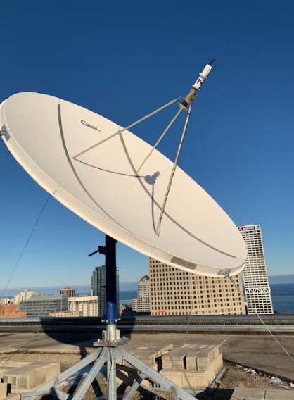
Waveguide bending is inevitable in radar, satellite communication and microwave transmission systems. In the installation of satellite antenna, the waveguide signal needs to be transmitted long distance between the antenna feed and the equipment room, and the linear arrangement cannot be achieved. In this case, the waveguide bending design should consider not only the space limitation, but also the signal integrity. For such applications, the use of flexible waveguides is a common choice, which allows for multiple bends at small angles and is extremely flexible, saving installation costs.
Compared with rigid waveguides and flexible waveguides, flexible waveguides are more expensive, the cost of a single meter is about 1.5 times that of rigid waveguides, but in complex systems, flexible waveguides often offset their high costs due to their ease of installation, reduced reflection and loss of efficiency. In some high-frequency communication systems, the insertion loss caused by waveguide bending may cause the overall transmission efficiency of the device to decrease by 30%.
High quality copper or aluminum alloy materials are often used in the manufacture of waveguides, especially those that require frequent bending. The price of copper waveguide is about 1000 yuan per meter, while the price of aluminum waveguide is only about 700 yuan, but the conductive efficiency of aluminum is about 20% lower than that of copper. For the transmission of high-frequency signals, copper waveguides are a better choice, because it can reduce high-frequency losses and improve the reliability and service life of the system.
Waveguide torsion
Waveguide torsion is achieved by rotating the waveguide in a progressive spiral shape, with common rotation angles of 45 degrees, 90 degrees, and 180 degrees. By gradually twisting the waveguide, the signal can change the direction of polarization while maintaining a low insertion loss. The standard WR-62 waveguide, for example, operates in the frequency range of 12.4 to 18 GHz, and when a 90-degree twist is performed, the insertion loss does not exceed 0.15 dB, ensuring that the signal remains of high quality during the twist.
When the transmitting polarization direction of the satellite antenna does not match the receiving antenna, the waveguide torsion can be used to align the transmitting signal with the receiving antenna to avoid the signal attenuation caused by the polarization mismatch. In some high-precision radar systems, errors in polarization direction can reduce signal efficiency by up to 20%.
In addition to polarization adjustment, waveguide torsion can also be used to solve the problem of space constraints, the installation space of the waveguide is limited, and the waveguide must be twisted to adapt to the physical structure of the device. In a high-frequency medical imaging device, the waveguide needs to bypass several mechanical components for transmission, and the path of the signal can be flexibly adjusted by twisting the waveguide without affecting the quality of the signal.
Waveguide torsion requires the use of high-quality conductive materials, the waveguide torsion component made of 99.99% pure copper, its signal loss can be maintained within 0.05 dB, and the use of silver-plated aluminum waveguide, its price is about 70% of the copper waveguide, but the electrical conductivity is poor, the signal loss is about 10% higher.
Waveguide torsion At lower frequencies, the effect of torsion is small, while in high frequency bands (such as millimeter wave frequencies), any change in polarization direction will significantly affect the propagation quality of the signal. To reduce these effects, twisting requires precise Angle design. A small deviation in polarization Angle may result in signal attenuation of up to 3 dB, which is equivalent to a 50% reduction in signal strength.
The design of waveguide torsion also affects the overall cost of the device. Taking a 90-degree waveguide twister as an example, the price of a twister manufactured with standard materials is about 2,000 yuan, while the price of a twister using high-end materials and precision machining is more than 4,000 yuan.