The forward directional coupler samples the forward-traveling wave with minimal effect on the main signal, while the backward coupler focuses on the reflected wave, offering enhanced sensitivity to mismatches in the system.
The Forward Directional Coupler
Working Principle
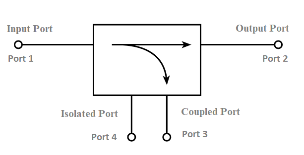
One of the most common types of couplers is forward directional ones. They are designed to direct and separate the incident and reflected signals along the device. It is based on the use of some fraction of the incident wave that can be used to measure it without changing its properties. in other words, forward couplers separate back from forward signals. In terms of physics is called the coupling factor measured in dB or other units.
Signal Routing
Due to its functionalities, such couplers have several important applications for signal routing, such as
Power monitoring: they allow measuring the power of the signal flow along RF and Microwave systems without breaking the main signal.
Signal Sampling: using such devices as oscilloscopes and signal analyzers, they are used to sample signals without tuning the oscilloscope
Antenna beamforming: in the case of phased array systems, such couplers allow controlling the amplitude and phase of the signal coming to each separate antenna
Advantages in Specific Systems
At the same time, this technology has several advantages and applications in the specific types of systems:
High isolation: usually over 20dB, forward couplers produce the minimal effect from the main flow to the coupled one.
Low insertion loss: it usually varies for 0.5 dB for such devices, transferring the signal with the less loss and preserving of the power.
Compact size: it is a feature mostly of modern devices that allow implementing it in various electronically filled devices due to their sizes
Broadband operating: due to the measure of the coupling coefficients, the range of their operation can be very broad.

The Backward Directional Coupler
Title: Application of Backward Directional Couplers
Working Principle
A backward directional coupler is designed to sample the backward wave, or that of which is reflected in a transmission line. This is achieved while keeping the effect on the forward wave to a minimum. This is possible due to the coupling mechanism, which couples the signal that is moving in the opposite direction. There is a quantification of the level of coupling, which is expressed in dB. A typical application of these devices is in the form of exciter couplers, bypass couplers, or broad-band couplers.
Unique Applications
Several unique applications of backward directional couplers include:
-
Reflected power monitoring;
-
VSWR measurement;
-
Protection circuits.
VSWR is a common and important parameter as it assesses the transmission line impedance. High values of this voltage accounting for mismatches have to be prevented and corrected. Backward directional couplers can also measure reflected power, which can be used to calculate VSWR. It is a common oversight that this quantity has to be first measured directly. There are various protection circuits that utilize these devices to protect units from the reflected wave. These are mainly used with high power levels in order to divert the excess reflected power.
Comparative Advantages
Some advantages of backward directional couplers as compared to forward directional couplers:
-
They are more sensitive to the reflected wave, which means they have a more direct approach to the measurement of the transmission pathway.
-
Since the backward versions of these devices can be specialized for measuring reflected power, they are cheaper. Similarly, the forward variation of these devices cannot be used in any of the applications specific to backward couplers.
Differences in Coupling Direction
The available variety of directional couplers available on the market allows for choosing the most applicable solution for different applications that require one-port in/one-port out signal processing and power sampling of the main and coupled lines. However, it should be noted that the direction of coupling contributes to the overall performance of a device by affecting different parameters.
Compatibility with Different Equipment
The differences in signal isolation depending on the direction of coupling could affect the compatibility of a directional coupler with other equipment in a larger system. For instance, a regulated frequency discriminator used in advanced radar systems depends on high isolation between signals on the input and output sides of the coupler . Therefore, a forward-type coupler appears to be the only suitable solution. However, in other applications, a backward coupler could be an optimal solution because higher isolation helps avoid the reflection of signals in the direction of their source. However, the need for a signal source in such devices typically imposes an additional requirement for backward couplers used in the sampling of reflected power. .
Implications for Power Handling
The direction of coupler coupling also influences its power handling capabilities. The forward-type coupler is designed to process the main line signal; meanwhile, the backward coupler processes the reflected signal, which is usually weaker and the device has a lower retention level.
Performance Analysis
-
Measuring Coupling Efficiency
Coupling efficiency is one of the essential metrics that determine the efficiency of a directional coupler. It is described as a ratio of power output at a coupled port to power input at a main one, generally in dB. In this way, if the coupling factor of a coupler is -10 dB, it means that 10% of power was coupled to the row of output. Accurate measurement is vital because it allows one to verify whether the coupler under consideration can meet the inputs and produces requirements.
-
Assessing Directionality Accuracy
Another critical parameter that determines the overall performance and efficiency is the directionality accuracy of a directional coupler. It measures the capability of a coupler to differentiate between forward and backward waves. Directionality value above 20 dB implies that a coupler is able to distinguish forward and backward waves and, in this way, this device is vital for a range of applications and procedures such as measuring Volt or Wave Standing Radio. Assessing this parameter is critical because it can determine the efficiency and accuracy of measurements at the output.
-
Understanding Return Loss and VSWR
Finally, other vital factors that determine the effectiveness and performance of a directional coupler are return loss and VSWR. The former is a value in dBs that measures how much power is reflected back to the source by mismatched impedance. In other words, the higher the return loss value is, the better impedance the coupler is. The latter is calculated as a ratio and it describes how the voltage standing wave ratio is distributed along a wireless device. The optimal VSWR is 1:1 in which case the impedance is matched. Both parameters allow one to understanding whether there are mismatches of impedance and take corrective actions.