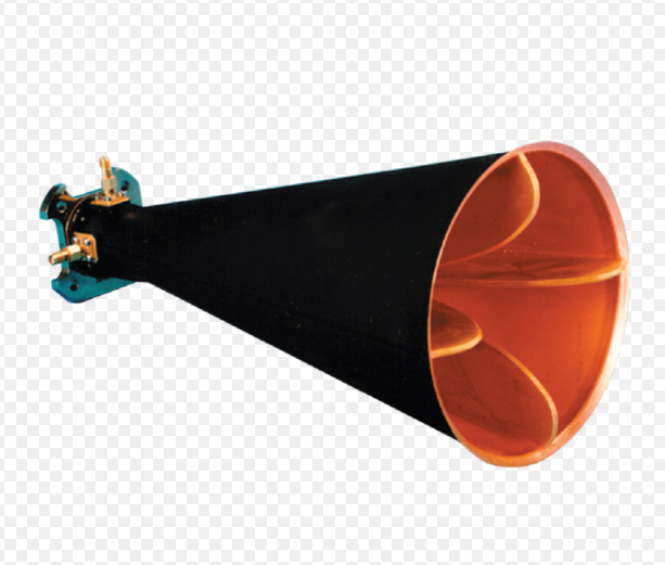
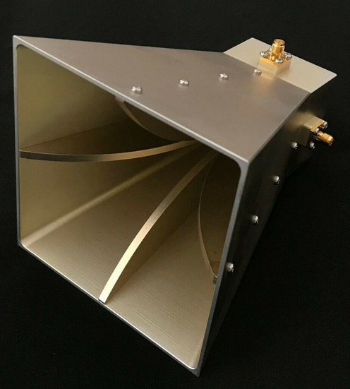
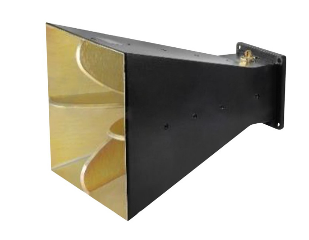
The beamwidth of a quad-ridged horn antenna varies with frequency. At 1 GHz, it’s typically around 60°, narrowing to 15° at 18 GHz. Measure it by sweeping angles in an anechoic chamber and recording points where power drops to -3 dB. Adjusting flare angle also fine-tunes beamwidth.
Frequency Dependency
The beamwidth in a quad-ridged horn antenna is a very important parameter, which changes quite dramatically with frequency. At lower frequencies, the beamwidth is generally broader, meaning the angular area covered by the antenna is greater. For example, at 1 GHz, for a typical quad-ridged horn antenna, the beamwidth in both E-plane and H-plane can be around 60°. This large beamwidth is of particular use in applications like wide-area EMC testing, where broad coverage is required for detecting emissions from large devices. However, when the frequency increases to 10 GHz, the beamwidth decreases significantly to approximately 25° to 30°, with higher directivity and increased spatial resolution.
Basically, the relationship can be further described by the fact that the size of the antenna aperture is relative to the signal’s wavelength. Considering a specific physical size of a quad-ridged horn, the wavelength decreases as the frequency increases. Such decreases the wavelength and thus increases the effective aperture in wavelength number. This results in a narrower beamwidth. The beamwidth at 2 GHz-for instance, in a quad-ridged horn with an aperture diameter of 10 cm-is wider (about 45°) where the wavelength is 15 cm, while at 18 GHz (with a wavelength of 1.67 cm), it narrows down to about 10°, thus allowing focused energy distribution and high-resolution applications including radar imaging.
In practical applications, frequency-dependent adjustments of beamwidth are decisive for scenarios demanding precision and flexibility. For example, GPR systems use quad-ridged horns at frequencies lower than 1 GHz to survey areas with beamwidths as wide as 70° to 80°. Conversely, the beamwidth of high-frequency airborne radar at 20 GHz can be less than 15° during a mapping exercise in order to achieve great details of small objects or other terrain features. This ability of changing beamwidth with operating frequency ensures efficient resource utilization and performance optimization for the wide range of tasks.

Polarization Influence
The polarization characteristics play a significant role in the performance of a quad-ridged horn antenna. These antennas are designed to support dual-linear polarization or circular polarization to offer flexibility in handling diverse signal requirements of an application. For instance, a quad-ridged horn operating at 3 GHz can easily achieve an XPD of about 25 dB, hence assuring very minimal interference between orthogonal polarization modes. This XPD value may decline to approximately 20 dB at higher frequencies, like 18 GHz, due to increased design challenges and manufacturing tolerances.
The polarization directly affects the beamwidth of the antenna in various planes. In the E-plane, the beamwidth at 10 GHz may be about 30°, while in the H-plane, the beamwidth might measure closer to 35°, reflecting slight asymmetries inherent in polarization handling. This difference is often utilized in applications such as weather radar systems, where dual-polarized quad-ridged horns are used in order to distinguish between raindrops and hailstones by comparing the backscattered signal strength in the two planes. These systems normally operate within the C-band frequency range of 4–8 GHz, where the beamwidths are carefully calibrated in both polarizations to enable accurate atmospheric measurements.
Polarization performance is also critical to reduce signal fading and improve link quality in communications. For example, a quad-ridged horn antenna may be used for Ku-band (12–18 GHz) applications and capable of providing return loss less than -10 dB for both polarizations: vertical and horizontal. This is very important for satellite communications since non-matching polarization results in substantial signal loss. For example, in a satellite uplink operating at 14 GHz, a dual-polarized quad-ridged horn with a beamwidth of 25° in both polarization planes could keep up a stable link even under the most adverse weather conditions since the dual polarization minimizes the effects of rain fade.

Wideband Capability
By definition, a quad-ridged horn antenna is wideband-capable, meaning it can operate effectively over a very wide frequency range. A typical quad-ridged horn antenna design would cover frequency ranges such as 1 GHz to 18 GHz and as broad as 0.5 GHz to 20 GHz, yielding a bandwidth ratio of 18:1 or greater. Such an antenna can operate within the range from 0.5 GHz to 20 GHz, enabling support of frequencies from low VHF to high Ku-band, which is very versatile for a number of applications such as spectrum monitoring and electromagnetic compatibility testing. This wideband performance dispenses with the requirement for several antennas to cover different frequency bands, reducing system complexity and testing time.
One of the critical aspects when dealing with wideband capability is maintaining consistent performance metrics throughout the frequency range. As a typical example, the VSWR (a measure of impedance matching) for high-quality quad-ridged horn antennas is typically below 2:1 within the operating range of interest. The main purpose is to ensure good power transfer with very limited signal reflections. In this regard, an antenna operating at 2 GHz might have a gain of about 10 dBi, whereas at 18 GHz, this could increase to about 20 dBi, showing that the aperture efficiency depends on frequency. This uniformity in gain over such a wide bandwidth extends the usability of this antenna in applications where the detection of signals over multiple bands is crucial, such as in electronic warfare.
Wideband capability also plays an important role in time-domain applications, such as ultra-wideband systems used in radar and imaging. The pulse fidelity achieved by a quad-ridged horn antenna in operation from 0.8 GHz to 18 GHz can be better than 85%, thus guaranteeing least distortion in the transmitted or received signal. This feature is especially useful in ground-penetrating radar systems, where high-resolution imaging of subsurface structures is required. For example, when scanning at depths up to 10 meters, the antenna’s wideband performance enables the system to effectively discern between soil layers and buried objects with resolution down to a few centimeters.

Beamwidth Control
Beamwidth is one of the most critical design parameters for a quad-ridged horn antenna. The beamwidth determines the coverage and directivity performances of an antenna. The manufacturer will be able to select the appropriate beamwidth for each application by changing some physical characteristics of the horn, such as flare angle and ridge geometry. For instance, for a flare angle of 25 degrees, the beamwidth of a quad-ridged horn antenna can be about 60° at 2 GHz for broad coverage in electromagnetic compatibility testing, while increasing this flare angle to 40 degrees extends the beamwidth to about 80° at the same frequency in applications that require large-area illumination.
Control of beamwidth depends strongly on frequency. Because the wavelength is much finer with increased frequency, the beam naturally gets narrower. A typical quad-ridged horn antenna operating over a frequency range from 1 GHz to 18 GHz could have a beamwidth of 50° at 1 GHz, narrowing to 30° at 10 GHz, and further to 15° at 18 GHz. This frequency-dependent reduction of beamwidth is very favorable for applications in high-frequency ranges, as used in radar systems where focused beams are necessary for correct target tracking. For example, for a 15 GHz frequency radar, 20° beamwidth means that the spatial resolution of an object at 5 kilometers away would be approximately 1 meter.
In the case of satellite communications, however, the control of beamwidth ensures effective signal coverage with minimal interference. The beamwidth can be as low as 25° at 14 GHz for a quad-ridged horn antenna to keep the link stable with geostationary satellites. Since the ridge structure can be modified inside the horn, the beamwidth can be fine-tuned to get higher gain and lesser side lobes, hence yielding better signal quality. For instance, in a Ku-band uplink system, it is critical to control the beamwidth to ensure the gain of at least 20 dBi while side lobe levels should remain below -10 dB to avoid interference with adjacent satellites.
Directivity Relation
One of the most salient features of a quad-ridged horn antenna is its directivity, which is inherently related to beamwidth. As the beamwidth decreases, the directivity increases, allowing the antenna to project more power in a particular direction. For instance, a quad-ridged horn antenna at 1 GHz can have a directivity of about 10 dBi with a beamwidth of 60°. While this is almost directivity at the frequency of operation, by 10 GHz, the directivity increases to about 20 dBi as the beamwidth reduces to 25°. This relationship is very important in applications where focused energy transmission or reception is needed, such as in radar systems or satellite communication.
The directivity of a quad-ridged horn antenna is also a function of the aperture size relative to the operating wavelength. For an antenna with an aperture of 15 cm, operating at 2 GHz (wavelength = 15 cm), the directivity is normally in the region of 12 dBi. At 18 GHz–wavelength 1.67 cm-with the same aperture, the directivity rises to almost 25 dBi. This sharp rise shows the dependence of directivity on wavelength and underlines the important role aperture dimensions play in antenna design.
In real applications, the high directivity of quad-ridged horn antennas enables them to reduce interference and improve the signal-to-noise ratio. For instance, satellite uplinks operating within the Ku-band, 12–18 GHz, are assured of efficient communication with a satellite even under adverse conditions such as atmospheric attenuation with a directivity of 22 dBi. Similarly, targets can be detected by a radar system operating at 15 GHz, with an angular resolution as fine as 1 degree, because of the high directivity; this makes precise tracking of objects possible up to a distance of 10 kilometers.
Measurement Units
Units of measurement are essential to carry out a definition in the performance and characteristics of quad-ridged horn antennas. Beamwidth generally refers to the angular spread of the main lobe in the radiation pattern and is usually measured in degrees. A typical quad-ridged horn antenna could have a beamwidth of 50° at 2 GHz, while at 18 GHz, this drops further to about 15°. The degree enables comparisons with great accuracy over different antennas and frequency ranges; therefore, it is the standard unit of measurement within the industry for angular measurements.
The other very important parameter is the directivity, given in decibels referenced to an isotropic radiator (dBi). At 1 GHz, a quad-ridged horn antenna may have a directivity of 10 dBi while at 10 GHz, because of the better focusing of radiated energy, the directivity increases to 20 dBi. This logarithmic scale is convenient for representing the large range of values of directivity encountered over a range of frequencies. For instance, increasing 3 dBi represents a doubled effective radiated power in a certain direction. The measurement units are thus important in evaluating the performance.
Voltage Standing Wave Ratio (VSWR) is employed for impedance matching, and it is a unitless ratio. The better-performing quad-ridged horn antennas maintain a VSWR of less than 2:1 over the operational frequency, for instance, from 1 GHz up to 18 GHz. This value characterizes efficient power transfer between the antenna and the connected transmission line. For example, at 5 GHz, the VSWR of 1.5:1 means about 4% reflected power, which of course provides a minimum loss of the signal to work within demanding environmental conditions such as electromagnetic compatibility testing.
Pattern Variability
Pattern variability in quad-ridged horn antennas is described with respect to changes in radiation pattern as a function of frequency, polarization, or physical design. A typical quad-ridged horn antenna at low frequencies, say 1 GHz, would have an approximate beamwidth of 60° to 70°, with about uniform side lobe levels of -15 dB. As this increases to 10 GHz, the main lobe reduces down to approximately 25°, while the side lobes grow in magnitude and can often rise to levels of -10 dB as a result of higher-order modes present in the radiation pattern. This variability requires careful design to balance main lobe efficiency with side lobe suppression.
Polarization significantly impacts pattern variability. In the case of an antenna operating at 5 GHz, for instance, the radiation pattern of the E-plane can have a beamwidth of 50° while the pattern of the H-plane can be 55°. This asymmetry becomes more pronounced with higher frequencies; for example, at 15 GHz, it could narrow to 20° in the E-plane, whereas in the H-plane, it could be slightly wider at 25°. This variability is often used to great advantage in applications such as dual-polarized radar systems, where the differences between polarization planes can be used to enhance object detection and classification.
Frequency scaling introduces additional pattern variability, especially in the placement and amplitude of side lobes. For example, at 2 GHz, the first side lobe may appear at an angle of 80° with an amplitude of -20 dB relative to the main lobe. At 12 GHz, the side lobe is closer to the main lobe at 50° with an amplitude of -15 dB. This shift happens due to the reduction of wavelength and increased aperture efficiency at higher frequency. Keeping the above changes within control is very critical in communication applications such as satellite communication where the side lobe level should be much lower in order to avoid interference with other adjacent satellites.


