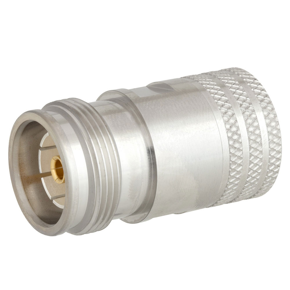
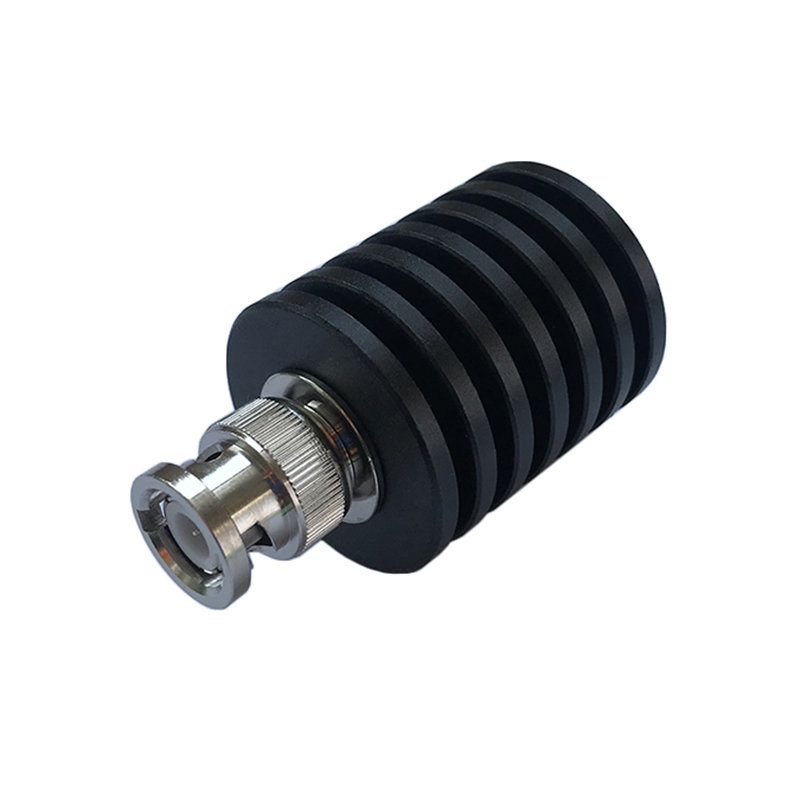
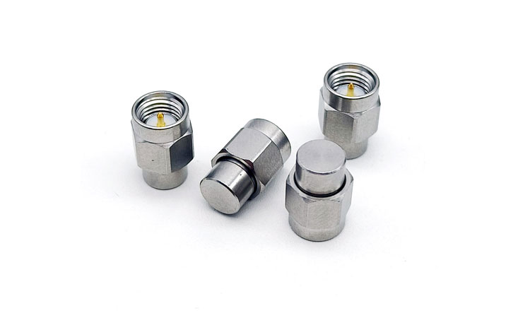
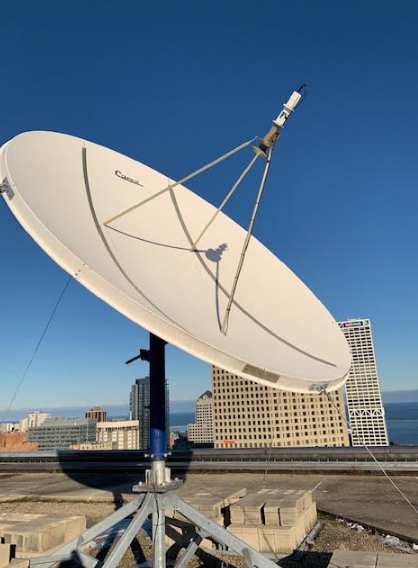
An RF termination is a passive component designed to absorb excess signal power in RF systems, typically with an impedance of 50 ohms. For example, a 100-watt RF termination can manage signals up to 18 GHz while maintaining a return loss greater than 20 dB, ensuring only 1% of the signal reflects back for optimal performance.
Definition
RF termination plays a vital role in radio frequency systems where it effectively absorbs the signal energy in order to avoid reflections. Usually, these types of terminations are designed to be matched with a characteristic impedance in the interest of 50 ohms or 75 ohms so that the integrity of the signal is preserved. Improper termination in typical RF transmission normally results in a high reflection coefficient about 0.9, which implies that 81% of the signal reflects back. A reflection at this order may lead to a severe degradation in performance for applications needing clarity of the signal, such as cellular communications.
The capability of RF terminations for power-handling ranges from very low-power types-rated between 1 and 10 watts-to extremely high-power types-rated above 1 kW. A general-purpose 50-ohm RF termination would be rated for at least 200 watts and would comfortably provide continuous operation in a high-frequency amplifier application. In contrast, an amateur radio application using a consumer-grade RF termination might be rated for only about 10 watts or so, depending on the specifications called for.
The frequency range is another very important factor in RF terminations. Most of the standard terminations will serve very well in the range from DC to 6 GHz. A microwave termination might be designed, for instance, with frequencies as high as 18 GHz, and thus be ideal for applications such as satellite communications or radar systems. That means these terminations at higher frequencies play a very important performance role since any mismatch increases insertion loss, which can easily exceed 0.5 dB at high frequencies, impacting overall system efficiency.
Cost is another significant factor in the selection of RF terminations. The industrial-grade, high quality RF termination may cost as much as $50 to $200, but an inferior version will be sufficient for consumer electronics, readily available for as low as $10 to $30. However, normally the investment in higher quality components yields a series of advantages in terms of reliability and length of life. For example, a really robust RF termination rated for 100 watts might last for more than 10 years in continuous use, but a much cheaper model might only work effectively for 2-3 years before it needs to be replaced, which just goes to prove the potential long-term value of the right product choice for a particular application.

Impedance Matching
Impedance matching is crucial for effective signal transfer in RF systems. Most RF applications require a specific impedance, commonly 50 ohms for most RF devices and 75 for cable television. In this case, the reflection coefficient would be ideal to zero when the impedance of the RF source, the load, and the transmission line all matched in. As an example, for 5-watt transmission, the system having a reflection coefficient of 0.1 will have 10% of the signal reflected together with a loss amounting up to as high as 0.5 watts.
A considerable degradation of the system can arise from a poor impedance match. In the case of wireless communications, an impedance mismatch can cause a greater distortion of the signal, amongst other effects, while lowering the SNR up to 30% or more. Studies indicate that for SNRs below 20 dB, mismatches which create a return loss of less than 20 dB may be able to lower the SNR. The SNR in cellular networks is critical and must be high with data rates above 20 dB for effective and efficient communication.
In addition, the costs caused by poor impedance matching accumulate over time. In an industrial setup of RF, poor impedance matching could lead to overheating and breakdown of equipment. For instance, a mismatched high-power amplifier would have its efficiency decreased by about 25%, meaning that it is wasting energy and most probably damaging parts that cost thousands of dollars. Actually, this could save companies as much as 20% of the operational cost on average if they invest in good-quality RF terminations that guarantee impedance matching.
Matching impedance networks are indispensable in the laboratory environment for the correct testing and calibration of RF components. This impedance matching is only one of the several techniques generally employed by engineers to increase the measurement accuracy. For instance, in the case where a new RF amplifier is being tested, a return loss better than 30 dB ensures less than 0.1% of the signal is reflected back and thus enables accurate measurements of the performance of the amplifier under test.

Signal Integrity
Signal integrity is one of the major concerns when it comes to RF systems, in that it impinges on the quality and dependability with which data can be conveyed. Among the very fundamental functions that RF terminations perform is the absorption of excess signal energy so as to suppress reflections. For instance, in an average RF transmission line, the return loss should be above 20 dB to ensure that less than 1% of the signal reflects back for clarity and strength in the signal being transmitted. In relation, a return loss below 10 dB allows for over 10% reflection rate, which can lead to partial data loss or probable communication errors.
Signal integrity is very important when considering system-level performance in high-frequency applications. In modern wireless communication systems with frequencies in the GHz range, even very small reflections can give rise to considerable distortions. Consider a 2.4 GHz signal, as is found in most Wi-Fi applications; its wavelength is approximately 12.5 cm. When reflections occur, they will lead to phase shifts and thus destroy coherent transmission and degrade throughput. According to research, this frequency can lead to a loss of data rate in a 1 Mbps range when there is only 5% reflection, where it affects the user experience considerably in environments of high demands.
Practically, the cost implications that might be incurred upon compromised signal integrity can be enormous. In the case of telecommunications, for example, a poorly terminated line of RF results in increased running expenses. A good example is that in the case of a base station with 25% efficiency loss because of problems in signal integrity, it can build up costs in power. Assuming a station would use 500 watts of power, this inefficiency would correspond to an extra $1,500 annually at an average electricity rate of $0.10/kWh. All these can be avoided by ensuring proper terminations.
RF systems also have signal integrity testing that can involve some pretty advanced equipment to precisely quantify the performance metrics of interest. For instance, the engineers will use a network analyzer to measure key parameters like insertion loss, which, for an effective RF system, should be less than 0.5 dB. When insertion loss is more than that, then that shows that something may be going wrong with the signal integrity, probably due to improper termination. For example, if in a transmission line an insertion loss is measured to be 1 dB at 1 GHz, this already represents a loss of almost 20% in the power of an input signal and states how optimal signal integrity is crucial to having robust communications in RF.

Applications
The areas of application of RF terminations in telecommunications and electronics are very wide. One of the most important application areas is that of wireless communication systems, where termination plays an important role in the proper transmission of the signal. In cellular networks, for instance, RF terminations reduce reflections that cause dropped calls. This becomes very minimal when a well-designed RF termination is used, rated at 50 ohms, and can greatly reduce the return loss to levels greater than 20 dB, meaning only 1% of the signal reflects back. This kind of performance is critical for high-quality voice and data services.
In broadcast television, RF terminations also play an important role in signal reception. Most television antennas have been designed for operation between 470 and 806 MHz. A specific RF termination at this frequency can really improve the clarity of a signal and decrease ghosting effects. For example, properly terminated 75-ohm coaxial cables can minimize multipath interference that may go as high as 30% in urban areas where there are several surfaces off which signals can reflect. Minimizing reflections allows a broadcaster to ensure there is a clear picture and better sound quality for the viewer.
RF terminations have a wider circle of application industrially, particularly in the areas of radar and telemetry. In this respect, radar installations require maintenance of signal integrity for proper target detection. Hence, high-power RF termination with an input capacity up to 1 kW is used to ensure the signals do not reflect back to the transmitter, thereby leading to overheating and possible failure of the equipment. For example, while the operational frequency of a radar system is 10 GHz, minor mismatching would have an approximate effect on 10% power loss, hence rendering the whole system inefficient in pursuing fast-moving targets.
RF terminations play an indispensable role in RF laboratories in both test and calibration applications. Many such applications require more accurate measurements of new devices for which the engineers seek. One typical case is that VNAs are put into use in pairs with RF terminations to provide very accurate insertion loss measurements. If the insertion loss for a certain termination at a frequency of 1 GHz is 0.2 dB, it means very accurate testing, which will ensure the conformance of the devices being tested against tight industry requirements.
Passive Component
RF terminations are considered passive components since they are used for the purpose of handling signal integrity in an RF system and do not amplify any signals. In contrast, all other active components have a power supply whereas RF terminations do not need those but perform the task only with resistive elements. A typical 50-ohm RF termination will be rated at 100 watts and can operate on very high-frequency signals with no distortion; hence, it becomes imperative in broadcasting and telecommunications. In each of these, there is no active circuitry to inject more noise into the system; hence, the signal remains uncompromised in its original form.
The power handling ability for passive RF terminations varies considerably. Most normal terminations are rated for low to moderate power and range from 1 watt to 50 watts. The high-power RF terminations, on the other hand, can handle up to 5 kilowatts, especially in industrial atmospheres such as those used by RF heating systems or high-power transmitters. For instance, a 500 W termination deployed in a military radar system guarantees that at maximum load conditions, the chances of signal reflection and overheating are minimized, thus making the entire system more reliable.
Another salient feature of passive RF terminations is temperature stability. Those elements might include temperature-sensitive resistive elements that could affect performance. Many of the good RF terminations are specified or designed to operate within temperature ranges from -55°C to +125°C. A typical industrial-grade termination maintains its specified impedance and power rating across this temperature spectrum for the most consistent performance under extreme environmental conditions. This is the reliability one needs to have in applications like satellite communications where the temperature fluctuations become major.
Besides temperature stability, many passive RF terminations usually possess low insertion loss characteristics. Insertion loss is basically the amount of signal power lost on account of the termination itself. High-performance terminations manage to realize insertion loss as low as 0.1 dB at frequencies extending up to 18 GHz. Efficiency at this level is of paramount importance in high-frequency applications, where even negligible losses can amount to substantial reduction in signal strength. For example, in a 10 watts system, an insertion loss of 0.1 dB means that only 0.4% of the signal power is lost, hence optimal transmission performance and higher overall system efficiency.
Thermal Dissipation
Thermal dissipation is one of the most important aspects in both the design and functionality of RF terminations. These components should be able to handle heating resulting from operation very efficiently, especially in high-power applications. For instance, a normal RF termination rated to handle 200 watts will exhibit considerable heat generation, reaching up to a temperature of 85°C within a few minutes of operation at full power. This is usually dissipated to prevent damage and ensure performance that is considered reliable. In practice, most manufacturers will usually feature these with a heat sink or some other type of cooling mechanism to manage this thermal output effectively.
The most important parameters, defining just how efficiently RF terminations can dissipate heat, will be the thermal resistance. The good RF termination has about 0.5°C/W of thermal resistance. That is to say, it means that with every watt of power dissipated, the temperature of the component increases by 0.5°C. As an example, if an RF termination is under operation with continuous power of 100 watts, the rise in temperature would be approximately 50°C above ambient. Thus, at normal room conditions of 25°C, the termination would reach 75°C, again stressing how vital it would be to have good thermal management.
In practical usage, the heat dissipation capacity marks the duration of time RF terminations will be operational. Components working at temperatures higher than ambient for periods of time can wear out quickly and finally fail. Indeed, studies have indicated that with a rise in operational temperature by 10°C, the life expectancy of electronic components is reduced by half. Such an RF termination rated for 100 watts, for example, may have its operational life reduced from 10 years at 70°C down to 5 years if the operating temperature runs at 80°C. This constitutes a very significant and observable reduction that calls for effective thermal dissipation strategies.
Testing and Calibration
Testing and calibration are important activities in determining the reliability and accuracy of RF terminations when used in the field. Engineers utilize VNAs to measure return loss and insertion loss, among other parameters, in the laboratory. For instance, a typical RF termination is tested for return loss to ensure that it is greater than 20 dB; that is, only 1% of the signal reflected. Such termination, unless not failed in this aspect, may cause serious performance-related problems like signal distortion or loss of efficiency in high-frequency applications where accuracy is indispensable.
The calibration of RF termination should therefore be done with various stages of frequencies for its consistent performance. A properly designed termination could work from DC up to 18 GHz without any failure but may require the testing confirmation on whether its impedance will remain stable throughout this spectrum. Take as an example a 50-ohm RF termination. Its impedance variations could be so great that they cause 15 dB return loss at some frequencies, not acceptable in high-performance RF systems. What engineers want is a flat response over the operating frequency range to ensure that insertion loss is maintained below 0.5 dB to maintain signal integrity.
The other side of calibration involves the measurement of thermal performance under load: that is, if there was a 200-watt RF termination under continuous power for a long duration, the temperature would be monitored by an engineer to make sure it does not rise above the acceptable limit of less than 85°C.


