The two most common values are coupling factor, often -3 dB to -20 dB, and directivity, typically 20 dB to 40 dB.
The Two Most Common Values of Directional Couplers
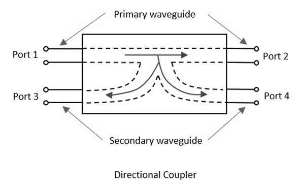
Directional couplers are instrumental in controlling signal paths in RF and microwave systems. There are two key values that these components are defined by, which are Coupling Factor and Directivity. Knowing about both of these values is key for ensuring the performance of the system and its effective use in RF and microwave applications.
The Coupling Factor
This value defines what part of power is transferred from the main line to the side line, or from one port to another, for the directional couplers with more than two ports. The optimal value depends on the needs of the system and the value should be the best compromised between signal transmitting and isolation.
Optimal values and their impact on the performance of the system: The value of the optimal coupling factor is determined by the needs of the system that needs to be coupled. There are several examples of values provided by Rod for use in different applications in the article. For instance, it ranges from -20 dB to -3 dB. The −3-dB value is one of the most widely used in the production of the microwave couplers . There it is called 3-dB coupler and is used for splitting the power, which is vital for microwave applications.
Material required and its impact on the performance: High-quality of materials and the exactness of parameters produced directly affect the coupling factor’s values for the coupler’s purpose. As the lower the drop of the coupling factor is, the more value is transmitted and the materials effect such things as insertion loss.
Directivity
It is the ability of a directional coupler to accurately differentiate the parameters of the forward and reverse traveling waves as a coupler’s parameter.
Optimal performance level and values required : The value for field-use processes is from 20 dB to 40 dB . In the case of 30 dB, the coupler is capable of distinguishing the forward and reflected waves which simplest example of use can be found in systems of power monitoring and network backup plans. The impact of design on values for directivity Design is of high influence; the exactness of spacing between lines of the coupler in it and the direct impact of its exactness with all of the requirements for the production procedures is direct on this value. Only with a high level of execution, the values comply with the requirements, and there is no other object possessing similar capabilities. I do believe that the created items are optimal for their intended uses. The comparison of these two values shows that while both of them are critical, they are designed to do different things. Coupling factor equals the amount of transmission signal is able to work with. In turn, the directivity is the value for which a meter is unable to divide between the forward and backward ways.

Technical Specifications of Directional Couplers
Directional couplers are essential devices in the domain of RF and microwave engineering, helping to guide signals based on their direction. The functionality of the coupler is defined by a number of technical parameters, including the Operating Frequency Range and the Insertion Loss [ Miller n.d. “New Planar 90 Degree Couplers Utilizing Two Low Cost General Couplers,” Directional Couplers ]. Studying the specifications, it is imperative to consider variability and other factors, such as application, materials, and the design of the directional coupler.
Operating Frequency Range
The Operating Frequency Range specifies the scope of signals over which the coupler is able to operate. The frequency range is significant because it acts as a measure to ensure the coupler works in a specific system.
Variability and Applications: Generally, a broader operating frequency range implies greater variability and more application. For instance, a high-frequency coupler ranging from 0.5 GHz to 18 GHz can be employed in a wide variety of applications, including broadband internet and aviation radar. However, when a specific application requires a narrower set of signals, the coupler might be designed to function in that range, such as 12.5 GHz to 14.5 GHz for satellite communication.
Material and Design Influence: The frequency range for operation is dependent on the materials and design of the coupler. The use of new dielectric materials can help expand the range because of the bandwidth increase. Furthermore, if the manufacturing process is accurate, the coupler will follow the design, helping establish the frequency range with less than 0.1 GHz tolerance.
Insertion Loss
Insertion Loss pertains to the decline in power when the coupler is inserted into the signal path. It is an important specification because the lower the loss, the more effective a coupler will be.
Benchmarking Lost Values: It is advisable to have less than 0.5 dB of insertion loss to preserve the power of the signal. Couplers may be employed in systems that require minimal loss, such as high-speed digital communication and precision measurements, and couplers may not reach the 1.5 dB loss.
Coupler Design: The structure of the coupler, including the number of internal pathways, as well as the materials employed, influence the level of signal loss. The path length, for instance, ought to be minimized to curb insertion loss. Moreover, low-loss materials have to be chosen as well as an accurate fabrication process to decrease loss. Thus, stability and waveguides of polymer as a construction material offer minimal loss and a coupler on the order of 0.5 dB.
Design and Construction of Directional Couplers
Introduction
The efficiency of routing RF signals with high precision by means of directional couplers strongly depends on their design and construction. Therefore, the application of specialized materials and advanced fabrication techniques is required.
Materials Used
The selection of materials for the construction of directional couplers is essential for defining the device’s performance, primarily in terms of insertion loss and operating frequency range.
Metals and Their Alternatives: Generally, high-conductivity metals as copper or silver are applied for the conductive parts of the couplers. They are characterized by low electrical resistance that reduces power loss. The dielectric is necessary to serve as insulation between the conductive pathways, and it should have low dielectric loss ensuring the signal transmission to be possible in the range of frequency required . For example, PTFE is a common material for this purpose due to its low loss and wide temperature stability range.
Innovative Materials: To promote performance of directional couplers, composite materials and nanoparticles are also applied. They make the coupler’s weight and size lower, while its efficiency remains or even becomes higher for operational purposes. For example, for high power handling of the coupler, it is critical to ensure good golf course and thermal conductivity, which can be provided by the use of graphene-based materials.
Fabrication Techniques
Such materials require advanced fabrication techniques to be used for the production of directional couplers due to the complexity of their properties and attributes. Manufacturing can be achieved by means of different precision techniques dependently on the design and material used.
Photolithography and Etching: In the case of microstrip and stripline couplers, photolithography is commonly used for the pattern definition by the conductive paths on the dielectric substrates, which is further defined by means of etching with the use of specific chemicals. It is crucial for high-frequency range operation, as even minor deviations from the precise width can severely affect performance. The accuracy of the method is characterized by the possibility to define the geometry of the whole series of the found components even with the feature sizes of 0.1 micrometers and smaller.
3D Printing and Additive Manufacturing: These techniques provide new opportunities for the fabrication of directional couplers, especially in the case of multi-layer and complex parts with complicated geometries. 3D printing, in particular, considerably reduces the production cost due to the high achievable precision while minimizing waste . For example, it allows engineers to create a prototype within hours and test it, which results in a shorter design cycle. In conclusion, the integration of advanced materials and new techniques of fabrication stands behind the creation of directional couplers meeting the requirements. The understanding of the processes and materials involved allows to apply and modify the existing design and achieve remarkable results in terms of coupler’s efficiency.
Types of Directional Couplers
Directional couplers play a significant role in RF and microwave systems by allowing the accurate routing and measurement of signal power. There are various types of these couplers, namely, the conventional, the microstrip and stripline, and waveguide and dielectric waveguide couplers. The differences between these types relate to their design, operational efficacy, and specific advantages for applications. Conventional couplers are the first type of such devices, typically equipped in RF systems with the help of waveguides or in form of coaxial couplers.
Waveguide Couplers. These type of couplers are characterized by excellent capability for handling power at high levels and low insertion loss. This advantage makes this type of couplers unique for radar and satellite communication systems, by preserving the signal integrity at an extremely high power of several kilowatts . The insertion losses of the waveguide type of directional couplers would normally not exceed 0.1 dB .
Coaxial Couplers. The advantages of this type of couplers include its flexibility for all frequency ranges and reliability of use in commercial and military applications. The frequency ranges of this type of couplers remain quite wide, at a few MHz to over 40 GHz . The benefit of coaxial design is its extra-robustness and easiness in implementation in the operational RF systems, while the drawback is the excessive weight and size in comparison to the planar technologies.
Microstrip and Stripline Couplers
Microstrip Couplers. Advantages of this type of couplers are its miniature size and ease of fabrication as part of printed circuit board differences . Therefore, microstrip couplers are perfect for the applications needing the smallest possible size, such as Rf devices and microphones used in wireless communication. Disadvantages of this type of couplers remain in the relatively high insertion losses due to fundamental limitations of the microstrip coupler design, normally accounting for 0.2 to 0.5 dB .
Stripline Couplers. These types of products form a balance between performance and compactness, providing fully enclosed conductive paths which eliminate the risks of external inferences. This design leads to the same insertion loss as shown by the microstrip type of couplers, but to much higher isolation performance-specific parameters for the stripline coupler . Hence, the selection of material will mainly depend on the specifics of performance requirements, such as the level of energy, size of microelements in operation, their loads, and costs. In summary, while the conventional type of couplers works best for high-power and wide frequency applications, microstrip and stripline couplers appear more advantageous in terms of integration and size proliferation, given the necessity of this latter quality for modern RF and microwave applications. The type of material is also very important, from conventional metals and alloys to the most advanced in their properties dielectrics.