The key parameters to describe antenna performance include gain, bandwidth, radiation pattern, VSWR, and polarization.
Gain
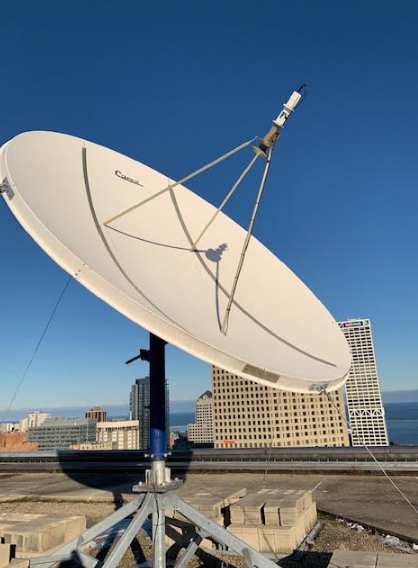
The gain determines the efficiency of an antenna by how much energy it can focus in a particular direction compared to an isotropic radiator. The latter radiates energy evenly in all directions to maximize loss and inefficiency. Typically, gain is expressed in dBi, which gives the number of decibels relative to isotropic over how much energy the antenna can transmit or receive in the desired direction. The level of gain has a substantial impact on the applicability of electronic communication devices. For example, a satellite dish has a very high gain, as the signal sent by the communication satellites in the geostationary orbit approximately 35,786 kilometers above the Earth’s surface is too weak to be caught otherwise.
In these cases, a higher-gain antenna is crucial for receiving weak satellite signals. Similarly, at home, the local Wi-Fi router most likely has an antenna gain of 5 dBi, which is enough to cover a few rooms. However, when it comes to long-distance communication devices, one would observe a much higher gain, with the value of 24 dBi or more. Such an antenna transmits a narrow beam of radiofrequency used to bridge distances of up to several kilometers.
The choice of a suitable antenna gain depends on the requirements of the communication system in terms of range and signal quality and two other beneficial factors: the higher the gain, the lower the power, and the smaller the size. For example, by replacing a 9 dBi antenna with a 24 dBi one, one can extend the coverage of a wireless system from around 1.2 kilometers to five kilometers or more, providing a line-of-sight link between a relay antenna high above a hill and home use of the system. Conversely, in an urban environment, the reflection off buildings and other obstacles for the signal creates more complex propagation patterns, so moderate gain of around 12-15 dBi is better suited to balance range and coverage. It ensures a reliable signal in any urban area, boosting the efficiency of mobile and fixed wireless networks.
Bandwidth
In our context, bandwidth is the range of frequencies over which an antenna can operate efficiently. It is vital to ensure that an antenna has enough bandwidth to support the required specifications for a given application. The relative bandwidth is the ratio of the bandwidth in Hertz to the frequency when talking in percent. The higher the relative bandwidth, the higher the bandwidth in Hertz. Bandwidth is essential to determine how much information an antenna can send and receive. A television set receives signals at broadband from many different channels. An ultra high frequency UHF antenna should cover a wide bandwidth range: from as low as 470MHz to 862MHz for instance, to receive digital TV broadcasts perfectly well on a television set. This specification ensures that the broadband antenna hog all the frequencies that reach it: the image never crackles, the problem never arises. An everyday case is when an access point combines WiFi access points sending data to different devices in the 2.4 and 5 GHz band like a wireless router. Hence, the bandwidth has a range varying from 20 to 160 MHz. Users with access to much higher speeds could use 1 Gbps and need to replace routers with dual antennas. The antennas will receive all radio and television signals. However, the antennas have to be much more complex and much more expensive to be able to handle such a frequency range.
Bandwidth represents the number of frequencies that an antenna is capable of processing at once. In that sense, antennas have a huge number of frequencies that define them. In professional settings such as mobile network base stations, bandwidth typically varies from several tens of MHz to several hundred MHz. This is because when five thousand users simultaneously shouting into their phones, there is a considerable bandwidth encoded in the audio, for instance. All these devices also stream high-definition videos that the mobile network must also support. In the end, the antennas in mobile network base stations are more complex and longer. However, in a home setting, the Yagi Uda is adequate and only needs to understand a single frequency. Note that the antennas are big because they have the sizes of approximately \frac{1}{2\lambda }. They are both easy to compute and easy to manufacture. They are able to fit on the SMS sender’s phone at a low cost. In the end, note that such considerations imply a tradeoff between bandwidth on one side, at the expense of either size or complexity on the other end.
Radiation Pattern
An antenna’s radiation pattern shows how the antenna transmits radio frequency energy or power in different directions, and is crucial for communication as well as system design. It is usually shown in a polar or Cartesian coordinate system, showing whether an antenna can focus or spread radio frequency energy. For instance, a good radiation pattern for a typical omnidirectional Wi-Fi router would be shaped in the form of a doughnut, as its radio waves are radiated in equal strength of power in all horizontal directions.
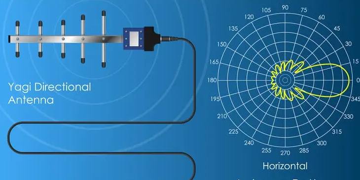
An omnidirectional Wi-Fi router’s radiation pattern is designed for optimal coverage in a residential house. The router’s radio waves have power logs with a sharp decrease as the elevation angle increases or decreases from the horizontal plane. This will guarantee a good signal on one side of the floor. For another example, a type of a directional antenna is the Yagi-Uda antenna, which is a typical rooftop antenna used for point-to-point Wi-Fi internet connections on rural service. Its strongest and main lobe beamwidth could be 40° and the beam on the radiation pattern would be more radiant than the usual noelogarithmic radiation patterns.
A Yagi-Uda antenna is a specifically directional antenna that can be utilized on a rooftop of a rural house and uses point-to-point internet conenction. When trying to comprehend why buying the right antenna would be optimal for better system design, large-scale networks such as a cellular base station is a perfect example of a complex design for antennae radiation patterns. A base station’s antennas might show multiple thin beams viewing at different angles, thus covering a bigg rectangular city. Its radio waves would be broadcast to have few obstacles, resulting in minimum intereference and a good service. For an example, a security camera system placed along the perimeter of a large warehouse fence. Each individual sector antenna has a radiation pattern in the form of 120°, which does not overlap with the other antennae from another radiation pattern.

VSWR (Voltage Standing Wave Ratio)
VSWR, which stands for Voltage Standing Wave Ratio, is a key metric that describes how effectively any given antenna is matched to both the transmission line and the transmitter. It denotes the ratio of the maximum to minimum voltages along the transmission line. This indicates how big of a proportion of the power being emitted by the transmitter is getting reflected back towards the transmitter. As far as a home Wi-Fi system is concerned, a good VSWR value would be something around 1.5:1 or lower for most people. It means that only a small fraction of the energy that is sent by the device is reflected back at the router, with an overwhelming majority powering the router or being signal radiated outwards by the antenna.
Such relatively low VSWR values are required by most people to have a properly working home Wi-Fi, as they directly affect its efficiency and signal strength. Different applications will have different requirements, for example, for an amateur radio system, or even a cellular base station, having a VSWR of around 1.2:1 would not be out of the question. The one added layer of complexity is that measuring the VSWR within such a small margin requires quite sensitive devices and subtle tuning of the antenna, which makes it a challenge. Reducing the VSWR from 1.5:1 to 1.2:1 is not just problematic, it is beneficial for the power transmission efficiency.
It means that the signal can send its energy from the earth entirely instead of having a portion of it bouncing back. This benefit is crucial for amateur radio operation, as it can allow people to send broadcasts over vast distances in order to achieve a wide reach for their audience. Additionally, it means that the transmitter does not have to work as hard to emit such a signal, which further contributes to slowing its wear and tear, a substantial consideration in the case of professional broadcasting equipment. However, achieving a desirable VSWR is not a trivial task. One has to utilize coaxial cables and connectors that are the best match for the antenna at hand, which might require precise manufacturing and delivery specifics. Many people in the field will also require a VSWR measurement to be undertaken across the operation bandwidth, which can require experimenting with the antenna placement, length, and angle. It is hard to get precise VSWR measurements without specialized equipment, such as a Standing Wave Ratio meter, which not everyone has access to.
Polarization
Polarization is the orientation of the electric field associated with the radio wave either transmitted or received by an antenna. It is an extremely important antenna departure parameter since it greatly affects the matching between transmission and reception on a communication systems. Antennas can have linear, circular, or elliptical polarization and the appropriate type will usually be chosen in order to optimize the efficiency of a communication and minimize the losses of the transmitted signal.
For example, in the common application of satellite TV broadcasting, antennas are always circularly polarized and are either left-hand or right-hand. The reason is that the circular polarization drastically reduces losses of signal caused due to signal degradations by the atmospheric is addition to physical obstructions. If the satellite is transmitting a signal to a home TV satellite dish, for instance, then the best polarization type to suit the dish’s receiving properties is RHCP since a left-hand signal may be distorted by rain and other structural disturbances that may occur in the path of the RF or microwave signal.
Another example is that most cellular phone systems are vertically or horizontally polarized. The reason for making the choice depends on whether one wishes to extend the coverage area or effectively penetrate urban building structures. For example, in densely populated areas, base station antennas at an urban area are arranged vertically. When a signal is transmitted with horizontal polarization, the radio waves do not interact sufficiently with the vertical conditioning of buildings and hence are largely reflected downwards. Therefore, money need not be spent on power and amplification to reflectively increase signal strength since penetrating the immediate area in the path of the received signal is normally sufficient. A case where the broadcast area is somewhat rural, the base station antennas are usually arranged horizontally in order to provide acceptable two-way coverage.
The desired effect is to avoid the technology, infrastructure, and concepts of urban city building. Base stations in sparsely populated areas may be mainly vertically polarized. Changes in polarity allow amateur radio operators to play with depolarization characteristics of given propagation conditions.When amateur radios make contact with each other and desire better communication over longer distance, depolarization can be used to reduce noise that normally hits the neighborhood against a vertical surface at ground level. The communication is clearer, especially when the consuming noise is man-made. The station with which the communication is intended sends a vertical signal as sent by the transmitter. Compared to when the amateur radios are broadcasting to a local population, it should be best for the horizon.. The relative costs of the vertical or horizontal pole are also a consideration. Producing an antenna capable of easily switching between the vertical and horizontal pole adds costs to the design. Some applications use sufficient fishing poles by using radio signals for long distances that they absolutely must be organized. On the same note, to monitor multiple baseline antennas across the local landscape, the monitoring site is idle and unapproachable, and the antenna rotates along with the poles of the radio signal.