To design an antenna for a specific frequency, first calculate the wavelength using λ=cf\lambda = \frac{c}{f}λ=fc, where ccc is the speed of light and fff is the frequency. For example, at 2.4 GHz, the wavelength is 12.5 cm. Then, select the appropriate antenna type (e.g., dipole or monopole), calculate the required length (e.g., 6.25 cm for a dipole at 2.4 GHz), and ensure impedance matching for optimal performance.
Determine the Operating Frequency
Determining the operating frequency of an antenna design is one of the most important first steps, since this determines many of the physical properties of the antenna and its performance. The operating frequency will affect the dimensions of the antenna, impedance matching, bandwidth, and materials of construction. For instance, in a typical Wi-Fi antenna designed to operate at 2.4 GHz, the wavelength is about 0.125 meters, or 12.5 cm. At this frequency, a half-wave dipole antenna would have an overall length of 0.25 meters in total, divided into two elements 12.5 centimeters long. A monopole, which is usually a quarter wavelength in size, would have a radiating element approximately 6.25 centimeters in length. This is a simple but effective design for consumer electronics, such as routers, where the antenna needs to be compact and efficient at a commonly used frequency band.
For higher frequencies, like those used in cellular networks, the design of the antenna becomes even more critical. For example, a 5G antenna operating at the frequency of 3.5 GHz, which falls into the mid-band frequencies of 5G, would have a wavelength of approximately 8.57 cm. This wavelength influences the size of the antenna elements. At 3.5 GHz, a quarter-wave monopole antenna would measure about 2.14 cm, which is a manageable size for modern smartphones and mobile devices. This compact size allows for high-density installations, which is why it would be ideal for integration into mobile devices and small cell towers. Antenna efficiency, polarization, and directivity at this frequency are also of essence for a reliable connection in dense urban environments.
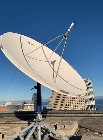
Satellite communication systems operate within GHz frequencies, typically from about 1 GHz up to 30 GHz. A communication antenna designed for operation at 12 GHz, for example, has a wavelength of 2.5 cm. These systems are also widely applied in satellite dishes, where the size of the antenna is critical for performance and cost reasons. At this frequency, the antenna needs to be precisely tuned to avoid losses that could impact signal quality. For example, if a parabolic antenna operates at 12 GHz, then it should have a diameter of approximately 30 cm in order to provide the expected gain and directivity. High-grade aluminum or composite materials are some of the materials used because this minimizes weight yet is highly efficient.

Select Antenna Type
The appropriate type of antenna at a given frequency should therefore be selected in order to achieve the required performance, efficiency, and coverage. The type of antenna affects fundamental parameters: gain, radiation pattern, polarization, and bandwidth. A half-wave dipole antenna is simple and adequate for many applications operating over a frequency range from approximately 30 MHz to about 3 GHz, covering radio and television broadcasting. For a 2.4 GHz Wi-Fi, it would be about 6.25 cm for a half-wave dipole antenna length per element and therefore compact enough to be carried around in consumer devices such as routers. At this frequency, the antenna provides good omnidirectional radiation; the energy is radiated, for all practical purposes, uniformly in all directions along a plane perpendicular to the antenna.
A parabolic reflector antenna is usually chosen for applications where directivity is needed, like satellite communication or high-precision radar. In such an antenna, signals are focused into a narrow beam, thereby increasing the gain and directivity. A parabolic antenna operating at 12 GHz might have a diameter of 30 cm to 60 cm, depending on the required gain. Such a kind of antenna will be very effective in long-range communications, for example, satellite dishes applied for broadcasting TV. That is explained by the large reflector which helps to effectively focus the signal, thus it manages to travel very long distances with minor losses. Actually, parabolic antennas can easily achieve gains of 30 dBi or even greater, much higher compared to omnidirectional antennas such as dipoles or monopoles. The trade-off for this high gain is a narrower beamwidth-meaning the antenna must be carefully aligned with the target for optimal signal reception.
Another common antenna type is the monopole antenna, which is often used for mobile communication systems such as cellular networks. A monopole antenna operating at 1.8 GHz-commonly used for 4G LTE networks-would have a wavelength of approximately 16.7 cm. A quarter-wave monopole antenna at this frequency would, then, have a length of approximately 4.175 cm. This antenna is usually mounted vertically above a ground plane and finds common usage in base stations and also mobile devices. It is of a relatively simple design with moderate gain and omnidirectional radiation characteristics. For higher frequencies, such as 5G, which is 3.5 GHz and above, monopole antennas are increasingly being used in small cell installations and urban environments due to their compact size and ability to provide broad coverage with relatively low complexity.
A patch antenna is often used for applications requiring compact and efficient antennas, such as in smartphones or GPS systems. The frequency range within which patch antennas find most applications ranges from 1 GHz to 10 GHz, as they are generally very compact, light in weight, and easily attached to objects. For example, a GPS antenna for the frequency 1.575 GHz will have a small patch with dimensions around 5×5 cm. Such types of antenna strike a reasonable balance among size, directivity, and performance. Patch antennas tend to be very effective with systems that must receive their signal from most directions, such as global positioning systems, without adding greatly to size or weight. Patch antennas may also be tuned to specified frequencies by altering the dimensions of the patch or the material in use, enabling them to be very adaptable for numerous wireless communication applications.

Calculate Antenna Length
Calculating the right antenna length is a crucial part of the design process, since it directly impacts the ability of the antenna to resonate at the intended frequency. The length of an antenna is determined based on the wavelength of the frequency it is designed to transmit or receive. In the case of a half-wave dipole antenna, the total length should be half of the wavelength; thus, for a 1 GHz frequency, the length is 15 cm.
One quarter of the wavelength is usually the length of an antenna in the case of a monopole antenna, widely used in mobile phones and wireless devices. At a frequency of 2.4 GHz-a frequency quite often applied in Wi-Fi systems, for example-the wavelength is 12.5 cm. Thus, the length of a quarter-wave monopole antenna would be about 3.125 cm at that frequency. Monopole antennas have compact dimensions, which is essential for many small devices where saving space is critical. The size of a monopole antenna is usually wavelength-dependent, but the physical size can often be reduced by the addition of tuning elements or various loading techniques that offer efficient performance.
The basic relationship between frequency and wavelength is given by the equation λ=cf\lambda = \frac{c}{f}λ=fc, where λ\lambdaλ is the wavelength, ccc is the speed of light (approximately 3×1083 \times 10^83×108 meters per second), and fff is the frequency in hertz. For example, when designing an antenna for a frequency of 1 GHz, the wavelength will be λ=3×10⁸ m/s1×109 Hz=0.3 m\lambda = \frac{3 \times 10^8 \, \text{m/s}}{1 \times 10^9 \, \text{Hz}} = 0.3 \, \text{m}λ=1×10⁹Hz3×108m/s=0.3m, meaning the wavelength is 30 cm.
For a more specific example, consider an antenna designed for FM radio, which typically operates in the 88 to 108 MHz range. To calculate the antenna length for a frequency of 100 MHz, we first calculate the wavelength:To calculate the antenna length for a frequency of 100 MHz, we first calculate the wavelength: λ=3×10⁸ m/s100×106 Hz=3 m\lambda = \frac{3 \times 10^8 \, \text{m/s}}{100 \times 10^6 \, \text{Hz}} = 3 \, \text{m}λ=100×106Hz3×108m/s=3m. The half-wave dipole antenna for this frequency would have a length of 1.5 meters, making it much larger than antennas designed for higher frequencies like those used in Wi-Fi or cellular networks.
The half-wave dipole antenna for this frequency would be 1.5 meters in length and thus considerably larger compared to higher frequency antennas such as those used for Wi-Fi and cellular systems. Its big size is suitable for broadcast towers where the antenna design is supposed to increase transmission range and area of view. In some instances, these kinds of antennas could be vertical or horizontal depending on the required radiation pattern.
However, the length of the antenna could be much smaller for higher-frequency applications, such as those in GPS systems. In the case of a GPS antenna, it normally operates on a frequency of 1.575 GHz, so that the wavelength is roughly about 19 cm. Then, a quarter-wave monopole antenna for GPS would have a length of approximately 4.75 cm. Because of this small size, GPS antennas can easily fit in portable devices like smartphones, wearables, and automotive systems. Despite the relatively small physical sizes, GPS antennas can still be very efficient at their design frequency, and the lengths can be further reduced with the use of patch or microstrip designs that make these antennas even more compact.

Account for Impedance Matching
Impedance matching is the most important aspect in antenna design and involves the assurance of maximum power transfers between an antenna and its transmission line. In antenna design, the antenna and the transmission line-e.g., the coaxial cable-must present the same impedance to avoid the reflection of the signal, leading to power loss and lower performance. The usual impedance value, which antennas are designed to have, is 50 ohms, as this is a standard value in most RF systems. A monopole antenna for 2.4 GHz, a common frequency for Wi-Fi devices, may be matched to a 50-ohm impedance transmission line. Without proper impedance matching, reflections can cause signal degradation; this is very harmful in communication systems, where the integrity of the signal is very important.
In case impedance cannot be matched between the antenna and transmission line, part of the power will reflect to the source. That is reflected power which cuts the energy that has to be radiated by an antenna; as such, its efficiency goes low. For instance, at a frequency of 2.4 GHz, the impedance of the antenna being 75 ohms and that of the transmission line being 50 ohms, there is partial reflection of the signal. The reflection coefficient can be calculated using the formula Γ=ZL−Z0ZL+Z0\Gamma = \frac{Z_{L} – Z_{0}}{Z_{L} + Z_{0}}Γ=ZL+Z0ZL−Z0, where ZLZ_{L}ZL is the impedance of the antenna and Z0Z_{0}Z0 is the impedance of the transmission line. In this case, with ZL=75 ohmsZ_{L} = 75 \, \text{ohms}ZL=75ohms and Z0=50 ohmsZ_{0} = 50 \, \text{ohms}Z0=50ohms, the reflection coefficient would be Γ=75−5075+50=0.2\Gamma = \frac{75 – 50}{75 + 50} = 0.2Γ=75+5075−50=0.2.That is, 20% of the signal reflects back, which further causes a huge loss in power and may lead to communications that are not reliable.
Impedance matching is done by various methods. The most common among them is the matching network, which adjusts the antenna impedance or the transmission line for a perfect match. The matching networks may be implemented as lumped components -capacitors and inductors-or may be distributed networks, using transformers or transmission line stubs. If the impedance of, say, an antenna is high, perhaps 200 ohms, and must be matched to a 50 ohm transmission line, then a quarter-wave transformer can be used.A quarter-wave transformer has an impedance that is the geometric mean of the two impedances: Zmatch=ZL×Z0Z_{match} = \sqrt{Z_{L} \times Z_{0}}Zmatch=ZL×Z0.
Choose Antenna Shape and Orientation
The shape and orientation of an antenna are very important in order to optimize its radiation pattern, gain, and efficiency. The shape and orientation of the antenna determine the way it radiates electromagnetic waves, and these characteristics can significantly affect the performance of the antenna in its specific application. For example, a dipole antenna has a simple linear shape. In fact, a most frequently used antenna type for a frequency spanning from 30 MHz up to 3 GHz takes this form. A common half-wave dipole antenna at a frequency of 2.4 GHz for a Wi-Fi system is approximately 12.5 cm long with its arms 6.25 cm each. It emanates omnidirectionally in the plane perpendicular to the axis of the antenna. Its simplicity and effectiveness make it an ideal choice for wireless communication in environments where uniform coverage in all directions is desired. The dipole’s radiation pattern is typically doughnut-shaped, with maximum radiation occurring in the horizontal plane.
For directional applications where focused signal transmission is required, such as satellite communications or radar, a parabolic reflector antenna is often used. Parabolic antennas take advantage of a parabolic reflector to focus the radiated signal into a narrow beam, increasing the gain and range of the antenna. A parabolic antenna designed for 12 GHz, for example, as used in satellite communication systems, may have a diameter of 60 cm or more. The larger the diameter of the reflector, the higher the antenna’s gain, which, in turn, improves the quality of the signal over long distances. The gain of a parabolic antenna can be as high as 45 dBi, which is quite higher compared to an omnidirectional antenna. This high gain is essential for long-range communication, where the signal needs to be focused on a specific target. Moreover, the parabolic antenna should be oriented precisely because even small misalignments can lead to a huge signal loss.
On the other hand, patch antennas are usually employed in applications that require compact size and high directivity, such as GPS or mobile communication devices. Patch antennas are flat, square, or rectangular in shape. They are very popular and work quite well within the frequency range of 1 GHz to 10 GHz. A GPS patch antenna for the 1.575 GHz might be around 5 cm × 5 cm. They basically radiate in a directional way with the main lobe of the radiation pattern concentrated in the direction of the face of the antenna. The patch antennas are normally mounted on devices such as smartphones, drones, and cars where space is limited for the installation of antennas. They normally lie horizontally or vertically depending on the requirements of the design, and due to their compact nature, it’s easy to integrate into small form-factor devices. While they are relatively small, patch antennas offer good performance in terms of stable reception when oriented in environments where the orientation of the antenna can be controlled, such as mounted in vehicles or wearable devices.
Optimize Bandwidth
Bandwidth optimization of an antenna is one of the most important aspects in the process of antenna design, since the ability of the antenna for the transmission or reception of radiations over a wide frequency range depends on it. Antenna bandwidth is generally expressed as the range of frequency over which the antenna performs effectively and is normally represented by the frequency range when the reflection coefficient is less than 2:1-or VSWR less than 2. For example, a dipole antenna optimized for 2.4 GHz-a common frequency in Wi-Fi-might be designed with approximately 100-MHz bandwidth and could, for that matter, cover the whole 2.4-GHz ISM band. It is wide enough to cover all the usual standards that operate in the 2.4-GHz range, such as 802.11b/g/n. If the bandwidth is too narrow, the antenna will only be able to function at a single frequency or a small range of frequencies, hence limiting its functionality.
Another effective way to optimize bandwidth is by using broadband antenna designs. These antennas are specifically designed to operate over a wide range of frequencies and can provide reliable performance for communication systems that require multi-frequency support. For instance, an LPDA antenna, widely used in applications like television broadcasting and communication systems, can achieve a bandwidth of up to 5:1 or more. For a system operating in the 100 MHz to 1 GHz frequency range, an LPDA could easily cover frequencies from 100 MHz to 500 MHz, providing flexibility and improved performance. With several elements of different lengths, LPDAs allow operation over wide frequency ranges, making them very suitable for applications in which the antenna should maintain a consistent performance for varying frequencies. Accompanying an increased bandwidth is usually reduced gain, but in systems where the operating frequency versatility is a plus, this may be a good trade-off.
Another method for optimizing bandwidth involves adjusting the physical dimensions of the antenna. By designing such antennas for wider bandwidth, some antennas can be built by making them larger or modifying the geometry; a possible broadband monopole antenna used in 4G LTE systems with frequencies of 1.7 GHz to 2.7 GHz can give a bandwidth of roughly 1 GHz. With the use of wide, tapered elements and additional impedance matching networks, the bandwidth of the monopole can be extended significantly. At 2.4 GHz, for instance, a normal monopole antenna may start off with 100 MHz of bandwidth but can, with the use of wideband loading techniques or the use of a larger ground plane, have its bandwidth expanded to include frequencies from 2.3 to 2.6 GHz and thereby be improved in performance in this crowding frequency band.
Consider Antenna Gain
The antenna gain is one of the major factors in determining how well an antenna radiates or receives electromagnetic waves in a specific direction. It is a measure of the ability of the antenna to focus energy in a particular direction compared to a reference antenna, usually an isotropic radiator, which radiates uniformly in all directions. The gain is usually expressed in decibels, dBi or dBd, where dBi represents the gain relative to an isotropic antenna and dBd is gain relative to a dipole antenna. A parabolic reflector antenna, which is commonly used for satellite communications, can achieve high values of gain in the range of 30 to 45 dBi, depending on the size and design of the reflector. This high gain makes parabolic antennas ideal for long-range communications, as they focus the signal into a narrow beam, increasing both the strength and directionality of the transmission.
On the other hand, an omnidirectional antenna-for example, a monopole antenna-usually has low gain. A monopole antenna is one that is usually used in mobile communication systems like cellular networks, where it has a gain of approximately 2 to 3 dBi. This lower gain results from the design of the antenna, which radiates energy uniformly in all directions around the vertical axis. For example, a 2.4 GHz monopole antenna, common in Wi-Fi systems, might have a gain of about 2.5 dBi, providing good uniform coverage for a Wi-Fi access point in a house or office. One advantage of an omnidirectional antenna is that it provides coverage in all directions, which is important in applications where the antenna must be able to communicate with devices at various angles, such as in mobile networks.
The gain of an antenna also depends on the frequency it operates on. Normally, as the frequency increases, so does the size of the antenna, and there may also be a relation between frequency increase and gain, depending on a number of factors that involve the design of the antenna, the environment around it, and its use. For instance, in the case of a log-periodic antenna normally used for TV reception or broadband communication, gain will vary with frequency. A log-periodic antenna that is designed for 500 MHz to 1 GHz could have a gain of approximately 6 to 10 dBi. The advantage of the log-periodic antenna is its wide frequency range, making it very flexible in systems that need to handle multiple channels or frequencies simultaneously.


