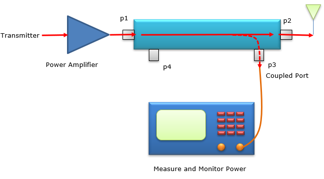
A directional coupler typically has two output ports: one main through port and one coupled port for signal sampling.
Design Variations and Characteristics of Directional Couplers
Directional couplers are essential for RF and microwave systems as they allow the energy of the signal to be sampled without significantly disrupting the signal itself. There are various designs, each being suited to a specific application type and performance requirements. First, it is necessary to distinguish between two general types, 2-port, and 4-port directional couplers.
The 2-port model is the simplest as there is an input and an output port. This type of coupler is typically used for signal splitting or combining while maintaining the signal’s integrity. The key advantage is that the applicability is straightforward, and the isolation factor is around 20 dB, with an insertion loss not exceeding 0.5 dB. The inherent simplicity of the design makes this model economical, but the efficiency does not make it suited for complex applications.
4-port models are more versatile as, in addition to the main line, there is also a coupled port and an isolated port to measure both the forward and reflected power while not interfering with the main signal. The isolation between the main line and the coupled port is above 30 dB, and the insertion losses are usually below 0.2 dB, meaning that this type is highly efficient . Overall, each of the parameters affects how the coupler performs in a system. Isolation is typically measured in dB and shows how well signal leakage is prevented between ports, meaning that high values are required for accurate sampling and minimal interference. Insertion loss indicates how much power is lost when the coupler is introduced into the path, with lower losses indicating superior performance. Directivity, another value that is measured in dB, shows how well the coupler is able to discern forward and reverse power, with the higher numbers being preferable. Finally, the voltage standing wave and its ratio will also affect signal reflection at the coupler’s ports, with low values being preferable.
Design Considerations and Their Impact
The use of various materials would impact the overall performance, cost, and even longevity of the directional couplers. High-quality dielectric materials such as PTFE or even air for insulation, as well as quality conductive paths including silver or gold, ensure low loss and high efficiency.Wth better materials comes a higher price ensuring the use of low-loss substances in the construction of the component. The size of the item and the overall form factor are also critical, especially when working with limited spatial conditions. Smaller sizes would regularly necessitate more advanced manufacturing methods . This would lead to an increased cost for the component while also allowing it to be more readily integrated into other systems. Further, the cost of the component is another significant consideration. In many cases, better materials and more precise manufacturing procedures would lead to better characteristics, but they would also increase the total cost of the item. For a commercial system, the designers might consider a coupler with 25 dB of isolation and 0.6 dB of insertion loss.
A military-grade equivalent might have an isolation of more than 40 dB and insertion losses up to 0.1 dB, but the item would also be more expensive for it . Finally, the overall efficiency, not just in terms of signal loss but electrical power used and heat created, is a key consideration. Efficient cooling systems might help with longevity of the item, and indeed the directional coupler can have very widely varied lifespan, down to five years and beyond fifteen years of operational time.
Operational Roles of Directional Coupler Ports
Directional couplers are a necessary element in RF and microwave communication systems, employing multiple ports to conduct a variety of crucial activities spanning signal sampling to power monitoring that serve to maintain system integrity and optimal function.
Signal Sampling and Power Monitoring
Signal sampling allows technicians to measure characteristics of a signal without impeding its flow. With a directional coupler, signal strength and quality can be measured by routing a fraction of the signal through a coupled port. A 4-port coupler is particularly good in this function as it offers a coupled port through which some of the signal’s energy can be extracted . The coupling value will typically be minus 20 dB, which would mean that the sample will be 1% of the power of the main signal. This ensures that the signal is large enough to analyze while still having minimal impact on the final output.
Power monitoring is of paramount importance for the optimal performance of the system. Directional couplers allow in situ monitoring of both the forward and reflected power and signal mismatches or system faults accordingly. Systems can easily monitor for deviations of 0.1 dB from the expected power levels and take necessary action.
Isolation and Termination Functions
Isolation prevents the signal source’s reflected signal from emulating the source by exiting through the input port. The high isolation value is useful for keeping the two ports functionally separate. Isolation above 30 dB from the source is ideal for preventing signal feedback, both distorting any measurements, and preventing damage to sensitive signal sources.
Termination works through the isolated port, which is usually matched to a load to effectively absorb the reflected energy, none of which exits the isolated port and continues to interfere with the signal’s integrity.
Reciprocal and Non-Reciprocal Use
The reciprocal use implies that the function of a directional is the same in both directions if the signal was going in either way. In a system that requires the bi-directional performance of the coupler to sample and monitor power in both directions . Non-Reciprocal Use is designed towards the function of a directional coupler for one-way operation which would allow continuing signal flow in one direction but would impede it from traveling the other way to prevent the reflected energy back at the source. This is a crucial function for devices such as antenna feeds, which need to remain isolated from any back-feeding to protect the system from both performance interference and faulty or damaged equipment.
Applications and Selection Based on Number of Ports
Directional couplers, a vital component in RF and microwave systems, are chosen based on their port configuration for specific applications, from signal routing to power monitoring and network analysis.
Selecting Applications for Coupler Type
2-Port Couplers are typically used in straightforward signal splitting or combining applications, where the interference with the signal path must be minimized to reduce system impact. They are used in cases where careful signal division is required with high efficiency, which often exceeds 90%, and low insertion loss, typically below 0.5 dB.
4-Port Couplers are used in more complex applications due to the ability to monitor both forward and reflected power simultaneously without affecting transmission. They are indispensable in complex systems that rely on accurate signal analysis to ensure that the frequency of interest is not disturbed. Their isolatedness, which exceeds 30 dB, reduces the interference in the carrier signal, making it an efficient sampling mechanism.
Bi-Directional Use
Bi-Directional Couplers are factory-configured for use in applications that require signal analysis in both directions. They are commonly used in duplex systems, communication networks where systems are required to have a two-way signal flow.
Dual Directional Applications
Dual Directional Couplers have separated measurement paths in the forward and reverse directions, allowing for equipment that measures power and SWR returns. They are used in testing applications and systems which rely on accurate measurement. Their directivity, which often exceeds 40 dB, provides highly accurate measurements.
Custom Coupling to System Requirements
Custom Coupling Values allow the user to precisely choose a specific portion of the signal to be sampled. A -10 dB coupling value may be chosen to ensure that the carrier signal only samples 10% of the transmitted signal and the rest is transmitted to optimize the system’s efficiency and reduce its impact.
Broadband Couplers
Broadband Use is critical for multiple applications, due to the need for the device to operate across a wide frequency range. Directional couplers have wideband operation available, which allows them to work across as many as several GHz or several MHz . Across the band, their VSWR and insertion lose stay low due to their coupling effect.