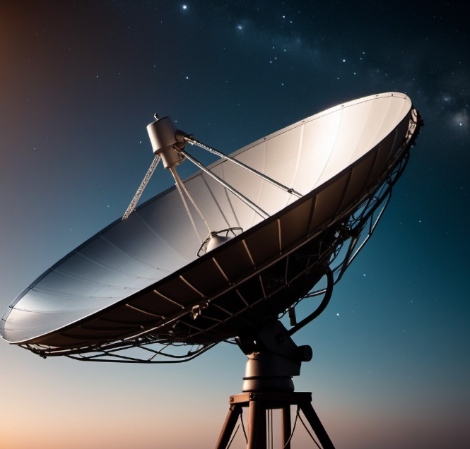
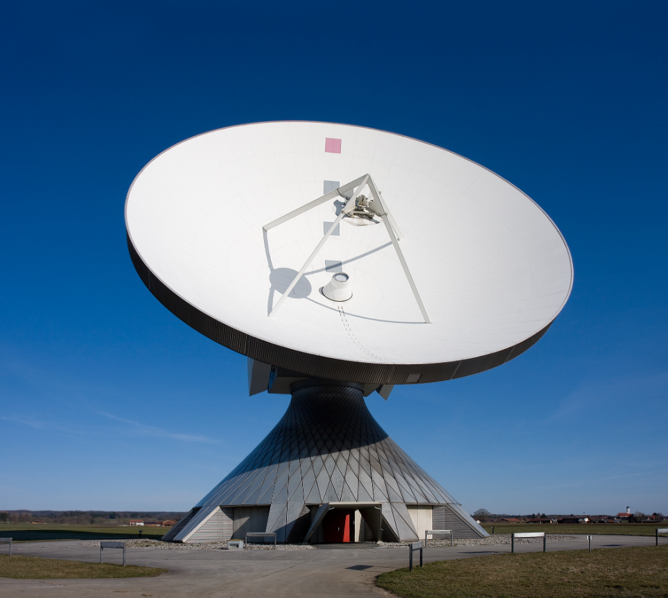
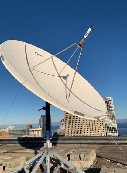
Satellite antennas focus signals using parabolic dishes, amplifying them with gains up to 55 dB for high frequencies like Ka-band (26.5-40 GHz). Proper alignment within 0.1 degrees ensures minimal loss, while advanced systems dynamically track satellites, enabling stable data rates up to 50 Mbps for internet and 4K broadcasting.
Signal Transmission and Reception
These satellite antennas depend on electromagnetic signals for their communication with Earth and orbiting satellites to deliver services such as television broadcasting, internet connectivity, and GPS navigation. Usually, the signal operates within a specific frequency band, including a Ku-band of 12-18 GHz for television or a Ka-band of 26.5-40 GHz for high-speed data. This is evident in the fact that DTH Ku-band signals are normally developed with 10-100 watts, and as such, cover wide areas. The other band, the Ka-band, supports faster data transfer rates up to 50 Mbps, key for the internet services. Proper alignment of satellite antennas with a specific frequency band is important to ensure minimum loss of signals, allowing transmission and reception to be very efficient.
Design and geometry of the antenna play a crucial role in signal quality. A typical parabolic dish antenna would have high gain, easily exceeding 35 dB for a Ku-band signal, which enables it to amplify very weak signals from satellites several thousand kilometers away. Reception would be best if the signal path between the dish and the satellite remains in line of sight without obstacles like buildings or trees. A slight mismatch of only 1 degree may result in a loss of up to 10-20% in signal strength, which directly influences internet speed or the clarity of TV. Installs, therefore, typically need antennas with narrower beamwidths, while rural installations are best served by larger dishes that can capture weaker signals.
Weather conditions also play a part in how the signal is transmitted and received. This is known as rain fade, a phenomenon where heavy rainfall weakens high-frequency signals such as those in the Ka-band; it causes a loss of up to 10 dB in signal strength. To rectify this, usually service providers install some sort of adaptive power control systems on satellites that increase transmission power to compensate for rain fade. While Ka-band internet services may drop, for example, from 50 to 30 Mbps in storms, Ku-band signals usually only lose around 3-5 Mbps in similar conditions. The largest dish size always benefits home users in areas with heavier rainfall, as a 90 cm dish will perform better than a 60 cm dish during adverse weather.

Parabolic Dish Design
The most common and efficient design of the satellite antenna is a parabolic dish, mainly because it focuses electromagnetic waves into a single point to maximize the signal. The operation of these dishes is based on reflecting incoming satellite signals onto a feedhorn located at the focal point. A typical parabolic dish can have a gain of about 35 to 45 dB for Ku-band frequency and up to 55 dB for Ka-band frequency, depending on the size. For instance, a 1.2-meter dish operating in the Ku-band offers approximately 40 dB gain, which enables clear reception of signals from satellites over 35,000 kilometers away.
The size of the parabolic dish directly dictates its performance. Larger dishes provide narrower beamwidths, which minimize interference from nearby satellites and terrestrial signals. For example, a 90-cm dish typically has a beamwidth of about 1.5 degrees, while a 1.8-meter dish reduces that to about 0.75 degrees. This improvement is crucial in applications that need high precision, like when transmitting data on densely populated satellite clusters. However, larger dishes are more sensitive to environmental factors such as wind and are thus equipped with sturdy mounting systems that maintain alignment.
Material selection is also an important factor in designing parabolic dishes. Most of the dishes are made of aluminum, which is lightweight and also reflecting. For example, an aluminum dish with a surface accuracy of 0.5 mm will have optimal signal reflection at frequencies up to 40 GHz used in Ka-band services. Large dishes designed for scientific applications may use carbon-fiber composites to reduce thermal expansion and maintain surface accuracy despite fluctuating temperatures. With such materials, the dish can have the high gain required for an application like deep-space communication.

Frequency Conversion
Frequency conversion in satellite communications is a critical process that enables signals to be efficiently sent for long distances and processed with ground equipment. Satellites use high frequencies, which range from 12 to 18 GHz for Ku-band and 26.5 to 40 GHz for Ka-band, minimizing interference and allowing high data rates. However, all these frequencies are not practical for direct use by receivers on the ground, and satellite antennas thus use frequency converters to lower them to IF ranges, typically from 950 MHz to 2150 MHz. This translation enables signals to be carried with minimum loss over standard coaxial cables.
The LNB converter, mounted on the dish antenna, performs this conversion in frequency. Modern LNBs boast of noise figures of as low as 0.3 dB, which gives a much clearer signal than that from older models whose noise figure was as high as 0.7 dB. For instance, an LNB operating in the Ka-band can amplify a weak satellite signal from -130 dBm to levels suitable for ground processing and simultaneously do frequency reduction from 30 GHz to a manageable IF. This capability is crucial for high-definition TV broadcasting and high-speed internet services, as it allows signals to travel with minimum degradation.
Frequency conversion is also critical in minimizing signal interference between multiple signals. Satellites operate through the use of FDM in separating uplink and downlink signals. For example, in the Ku-band, uplink frequencies operate within a range of 14-14.5 GHz, while downlink frequencies operate within 11.7-12.2 GHz. LNBs shift these high frequencies to IF for set-top box or modem compatibility. This ensures there is no signal overlap between uplink and downlink; thus, communication quality is assured. The lack of accurate frequency translation results in distorted or lost signals, which badly deteriorate services such as live broadcasting and video conferencing.

Line of Sight
Satellite antennas require a clear line of sight to establish a stable link with satellites in orbit. The antenna must have a clear path to the satellite since even small obstructions, such as trees or buildings, can weaken or totally block signals. For instance, up to 15 dB loss of signal can be caused by obstructions, which is highly detrimental to service quality in applications such as satellite television and the internet. To avoid this, antennas are normally fitted at high locations, such as rooftops, with an elevation angle starting from more than 30 degrees to minimize the effect of obstacles.
The distance to geostationary satellites at approximately 35,786 kilometers above the equator amplifies the need for precise line-of-sight alignment. At this range, a 1-degree misalignment can cause the antenna to miss the satellite by hundreds of kilometers, leading to a complete loss of signal. Modern installation practices involve the use of satellite signal meters, which ensure that alignment is within 0.1 degrees of accuracy. For residential installations, this level of precision is very critical to maintaining stable services, especially for high-definition television, which requires signal strengths of -70 dBm or better for good viewing quality.
Weather conditions may also affect the line of sight: rain, snow, or heavy clouds can result in the attenuation of signals, popularly known as rain fade. Ka-band signals operating within higher frequency ranges of 26.5-40 GHz are more susceptible, with losses up to 10 dB during extreme weather conditions. Contrariwise, Ku-band signals are less affected, being generally within 3-5 dB loss for such similar conditions. This calls for users in regions that have frequent heavy rainfall to make use of extra-large dish sizes or implement other error correction technologies capable of ensuring continuity of service.
Polarization
Polarization in satellite communication is extremely useful in differentiating signals and reducing interference among adjacent channels. Signals can either be transmitted and received using linear polarization, such as horizontal or vertical, or circular polarization, such as left-hand or right-hand. Linear polarization finds a wide application in Ku-band and Ka-band systems, where horizontal and vertical planes ensure clear separations of signals. For example, a satellite operating in the Ku-band with horizontal polarization may provide uplink frequencies at 14 GHz, while vertical polarization supports downlink frequencies at 12 GHz, thus allowing for efficient bidirectional communication.
The efficiency of polarization alignment directly affects the signal strength. A mismatch between antenna and polarization of the satellite leads to cross-polarization interference, which negatively affects the signal strength by up to 30%. For systems that handle residential satellite TV, even a 10-degree misalignment can lead to a loss of 2-3 dB, which might appear as pixelation or dropped channels. Most modern antennas have features for polarization adjustment, allowing users to fine-tune their antenna orientation to the satellite’s signal. This is most critical in high-frequency Ka-band systems, where precise polarization alignment ensures minimal interference and stable data rates exceeding 50 Mbps.
Weather conditions also affect polarization performance. Rain or high atmospheric moisture leads to depolarization; the polarization plane of the signal is deformed. The impact is more serious in circular polarizations and at high frequencies, such as in the Ka-band, where rain-induced depolarization can be up to 5 dB. In areas prone to heavy rain, service providers often implement adaptive technologies that change the angle of polarization in real time to maintain quality. For example, satellite internet systems with dynamic polarization tracking will stay connected through changing atmospheric conditions and reliably deliver consistent speeds through storms.
Beamwidth and Gain
Satellite antenna performance and efficiency in the transmission and reception of signals are determined by two basic characteristics: beamwidth and gain. Beamwidth is defined as the angular spread of the radiation pattern of an antenna. These are normally measured in degrees, while gain basically refers to how effectively an antenna amplifies signals and is measured in decibels. With a narrower beamwidth comes higher gain, enabling the antenna to concentrate most of its energy. For example, a 1.2-meter dish using the Ku-band has a beamwidth of approximately 1.8 degrees with a gain of about 40 dB, allowing for the most precise communication with distant satellites.
The relationship between beamwidth and antenna size is critical to system design. Larger antennas produce narrower beamwidths, reducing interference from adjacent satellites. For example, a 2.4-meter dish operating in the C-band can achieve a beamwidth of just 0.6 degrees, compared with 1.2 degrees for a 1.2-meter dish. This precision is crucial for crowded orbital environments in which satellites are spaced as close as 2 degrees apart. High-gain antennas, often in excess of 45 dB, are especially valuable for applications requiring strong, reliable signals, such as broadcasting high-definition television or supporting large-scale data networks.
Environmental factors also come into play when considering beamwidth and gain. Wind and structural vibrations can cause misalignment, reducing the effective gain of the antenna. A wind gust of 50 km/h can deflect a large dish by 0.2 degrees; such a shift in dish alignment can result in a 3-5 dB loss in signal strength. In order to minimize these effects, many high-performance antennas have rigid designs or dynamic stabilization systems that maintain alignment during adverse conditions. In addition, gain is a function of frequency: owing to the shorter wavelengths involved, Ka-band antennas exhibit a higher gain, up to 55 dB, compared with 35-45 dB for Ku-band systems of comparable size.
Downlink and Uplink Processes
The downlink and uplink are central to the process of satellite communication, enabling bidirectional data transfer between Earth stations and orbiting satellites. The uplink involves sending signals from a ground station to the satellite, which consists of high-frequency bands, typically 14-14.5 GHz in Ku-band or 27.5-30 GHz in Ka-band. Conversely, the downlink delivers signals from the satellite back to Earth, usually at lower frequencies, such as 11.7-12.2 GHz in the Ku-band or 17.7-20.2 GHz in the Ka-band. This frequency separation prevents interference between the two signal paths, ensuring clear communication.
Signal power is a critical factor in the uplink process. A typical ground station overcomes this problem through the use of a high power amplifier – typically output levels range from 50 to 500 watts. For instance, it takes considerable power to transmit a signal to a geostationary satellite distant 35,786 kilometers and still provide a received signal-to-noise ratio of at least 10 dB. Large dishes, of say 9 meters in diameter, have higher gain, such that over 60 dB in the C-band to help the uplink reach the satellites, even when there is serious interference due to bad weather conditions.
The downlink process, therefore, depends heavily on the transponder of the satellite to magnify and send the signal toward Earth. Each transponder typically operates within a bandwidth of 36 MHz, capable of supporting up to 40 Mbps for data-intensive applications like high-definition video streaming. However, signal strength diminishes as it travels through the atmosphere, experiencing losses of 2-5 dB due to factors like rain or cloud cover. Satellites, therefore, use high-gain antennas and onboard amplifiers to compensate, ensuring that the strength of the signal received at ground stations is above the required threshold of -70 dBm for reliable reception.


