Introducing corners and bends into waveguides can increase signal attenuation by up to 0.1 dB/bend, necessitating larger bend radii and signal boosters for optimal performance.
Reflections and Losses
Making the previously mentioned changes can also substantially change the manner in which signals are transmitted through a waveguide, creating reflection and loss. Both phenomena are highly relevant since they alter efficiency and predictive power in a waveguide system. When an electromagnetic wave encounters a corner or bend in the waveguide, an imperfect matching of impedance allows for part of the signal to return to the waveguide, which can partially nullify the usefulness of the waveguide and cause signal loss. An example of this problem includes optical fibers used in internet signal and data transmission, where any loss of signal might decrease data transfer speed and increase ping, further complicating connections. Even a 1% decrease in the strength of the signal at the arrival will cause a drop in transference speed, and after several turns, this loss continues to decrease the speed at which signals are transmitted, causing reduced overall efficiency and network performance.
This can obscure the risks involved in wasted spaces, like a 0.5 dB loss in a system that processes 100 Gbps at a point of space efficiency that requires a bend that leads to Sydney Networks. This loss can be adjusted if a system of 100 Gbps is meant to repeat a bend every 45 cm, causing the total data loss to be 10%, which fits 89 Gbps, and the overall level of space efficiency has now decreased. Because the efficiency of the network overall is essential for lowering space requirements and operational costs associated with it, even a small loss at the space of transition leads to a significant permanent decrease in space efficiency. Several methods for dealing with this issue include reducing the curvature or ensuring that any constructing materials have a relatively low loss tangent. The losses incurred by these bends can be reduced drastically with the use of gradual, large curves, from perhaps 1 dB in a turn to 0.1 dB from a 10 cm turn in a microwave waveguide. Materials with low loss tangents will also be more effective at transmitting signals, as some advanced microwave designs can reduce their losses per meter to 0.05 dB as a result.
Mode Conversion
One can consider the introduction of corners and bends to waveguides to be an effect of mode conversion, i.e. the transfer of waveguide’s energy from one mode to another. This effect is most severe in multimodal waveguides, which might be, for instance, an optical fiber or a microwave waveguide. Mode conversion contributes to a dramatic increase in losses and deterioration of transmitted signal’s properties, and it is widely used as a factor affecting system’s overall performance.
A multimodal fiber optics telecommunications system migth be used as a background example. When a corner or a bend is introduced into an optical multimode fiber, a higher-order mode is likely to be excited. However, the desired mode might be either lower-order or a combination of a few possible modes. This means that the propagating modes are mixed, which causes signal distortion and loss of quality. This is specifically severe in high-speed data transmission, when a high level of signal purity should be maintained to minimize bit error rates. In such systems, mode conversion effects might decrease system’s performance by up to dozens of percent. For instance, 0.5 dB consider modes conversion loss in 100 Gbps multimode fiber might lead to transmission distance degradation by up to 20%.
These problems are typically address by the use of mode scramblers or mode filters. A mode filter suppresses the higher-order modes, i.e. they are strongly attenuated. For example, for a microwave multimodal waveguide the attenuation might be typical 0.2 dB/km, whereas filtered modes might show 0.1 dB/km losses, which is 50% higher. This difference might be even bigger for larger waveguide lengths, thus the use of modes filters is advisable in long-distance systems. Mode scramblers, conversely, diminish the severity of the effect of modes conversion by scattering them in respective directions, towards waveguide’s walls.
The optimal design of corners and bends also substantially diminishes the effect of modes conversion. To have minimum losses, a waveguide’s bend should be as smooth, as possible, and its diameter should be as large as possible. For instance, a fiber bend radius should be over 1 mm, for microwave waveguides signal losses are close to no more than 1 dB for a 5-lambda radius waveguide bends, and exceed 1 dB for small 1-lambda bends. Finally, the quality of waveguide materials used might immensely affect modes conversion effects. For materials used in multimode fiber optics, a dielectric constant < 0.01 is usually classified as high quality.
Phase Distortion
Waveguides with corners/bends lead to a situation where the different sections of the signal receive a relative phase shift in proportion to the corner. As a result, the component of the phase factorality across the signal impairs the signal waveform, producing phase distortion. Some of the systems where phase distortion affects the performance appear in radars, communication networks, and high-frequency electronic circuits. Radars depend on the phased array aperture, where phase control systems are employed on the radar system to determine the distant object’s position of the signal. It results in the target being placed on the error of its actual position as the received power is considered at the reference line. Therefore, if waveguide conditions a phase shift of 10 degrees, the reflected unclear signal will be received at another location. When the radar system applies a signal of 10 GHz for the high-resolute radars, the phase factor of 1E is equivalent to several centimeters amplitude of the wavelength. The engineers engage various methods to manage the distortion. For instance, the use of end bends with a large radius to achieve per-phase distortion of 10 degrees. A sharp bend has per-phase distortion exceeding 10E due to the small radius of the waveguide. Such a design procedure maintains the signal state integrity on the waveguide wall. Additionally, some materials have a smart dielectric constant that is conducive for the WR90 series.
The other method involved the use of advanced materials with a low dielectric constant standard. The per-phase distortion up to 50% can be reduced by selecting a waveguide where the refractive index varies across the bands of frequencies; some of the materials that reduce the effect are polymers. Secondly, the use of flanges with annular rings can control the per-phase error of 10 degrees at 1 GHz. Finally, rectification can apply; the simulation requires special phase correction systems to be employed in an adaptive manner. As a result, these electronics can be employed in optical fibers hard with repeaters in such a way that the actual distance traveled can be 20% more. As a result, the devices are capable of running long fibers per fiber length without repetition.
Radiation Loss
Radiation loss is a phenomenon associated with waveguide bends and corners, where some of the electromagnetic energy leaks out of the waveguide. Thus, it operates less efficiently which is significant in terms of high-frequency operations. The loss of signal can occur only when the waveguide’s structure obstructs electromagnetic wave propagation, leading to radiation of a part of the energy away from the wave guideguide. Radiation loss is especially prominent at sharp bends and corners. For instance, in a microwave waveguide working at 10 GHz, when bend at 90 degrees, radiation loss can be up to 0.5 dB, which is 10% of the power of the signal. When one considers a signal that is to be transmitted over long distances, loss of signal performance accumulates, which may render the operation faulty.
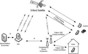
The satellite communication system using waveguides to connect various components are a good example. The radiation loss at bends can lead to signal attenuation, limiting the system ability to keep the signal as strong and clear as necessary over long distances. If one waveguide bend in the system leads to signal loss of 0.5 dB, then with ten bends in the system it will lead to 5 dB of signal loss. As result, the system will have extremely inefficient signal quality and will need additional amplifiers. To address those concerns, the system should have wide ban of frequency to allow for flexibility, requiring significant funds and manpower to be installed.
What do Electrical Engineers do to Limit Radiation Loss?
The ways to decrease radiation loss is to directly form bends with large radii, as it was mentioned before. If when using a bend of 3 wavelengths radius 5 GHz bend at 10 cm, leads to radiation loss of no more than 0.1 dB. In addition, the quality of the materials used can drastically affect radiation loss. High-quality materials can be created with a very low loss of tangent, for instance, it is as low as 0.0004, even when 10 GHz operation is concerned. The ideal way to reduce radiation loss would be through the use of a shield. Such a shield would block leaked energy from exiting the wave guide guide. This is very useful in microwave systems where even a small percentage of radiation loss can lead to great power loss.
Dispersion
The introduction of corners and bends in waveguides results in a phenomenon called dispersion, by which different frequencies of a signal propagate at different velocities. Dispersion causes the signal to spread and, essentially, to be distorted, thus it can have a major effect on the functioning of systems where timing and signal integrity are crucial. In particular, dispersion is a significant problem in optical fibers, which are widely used for high-speed internet and data transmission. When light signals travel through bends and corners, different wavelengths or modes of light experience varying delays and pulse broadening results. Specifically, in a common multimode fiber optic cable, a bend radius of 1 cm ensures that a 1 ns pulse will be broadened to last 1.5 ns such that the pulse duration increases by 50%. Thus, the data rate will be limited and the maximum transmission distance will be reduced without signal regeneration.
Let me provide a vivid example. Imagine a data center where the expansion of the network significantly depends on the speed of data transfer. If an optical fiber link is subject to significant dispersion due to multiple bends, the data rate may decrease from 100 Gbps to 80 Gbps. The reduction of the data rate affects performance of the whole network as well as leads to higher operational costs because more repeaters or signal processors are needed to maintain the data at the required rate over long distance.
In order to deal with dispersion in waveguides, engineers can deploy various methods and tools. One of the most effective solutions is to use waveguides with the bends made based on optimal bend radii. For instance, in the abovementioned optical fiber, modal dispersion and thus pulse broadening is minimized as the bend radius is no less than 10 cm. As a result, the maximum data rate is maintained along with the effective transmission distances. Apart from that, one can use dispersion-compensating fibers, where the effects of the dispersion in bends and corners are compensated by the refractive index profile. For example, the dispersion of a 100 km link using PCF is not 1 ps/nm-km or more, but it is less than 1 ps/nm-km, which is necessary to keep a data rate of 100 Gbps. Finally, signal processing tools and equipment can be used as another way to counteract the dispersion. For instance, digital signal processors can use pre-distortion or equalization algorithms to undo the effects of dispersion-induced pulse broadening. In a 100 Gbps optical communication system, DSPs can ensure that the dispersio-originated pulse broadening is kept in check for the system to maintain the required performance even over the distance with multiple bends. Finally, materials with low dispersion are becoming more and more popular in order to allow edges to be cut or sanded for specific applications to prevent transmission quality from degrading. For example, photonic crystal fibers can demonstrate, owing to certain degree of freedom in design, near-zero values of dispersion at definite wavelengths for high performance. A dispersion value of less than 0.5 ps/nm-km at 1550 nm in wavelength allows the performance of the signals traveling through the PCF in optical networks to be ensured at a high level with their high speed being preserved.
Increased Attenuation
Attenuation is one of the effects that placing corners and bends in waveguides has on signal strength and quality. Assuming that a waveguide carries an electromagnetic signal, attenuation is the loss of strength of signal as a function of distance. Cutting corners in waveguides, therefore, exacerbates the effect leading to increased energy dissipation in the corner and/or bend. This severally degrades signal quality and makes the waveguide extremely inefficient in signal transmission. This is more so when one wants to use waveguides in long-distance communication infrastructure including startup companies that attempt to build undersea fiber optic lines. Assuming that an optical fiber has an attenuation of about 0.2 dB/km for instance, additional attenuation corning in the fiber would make it less than inefficient for long-distance communication.
To illustrate, if a particular optical fiber has no bends, its attenuation would be 0.2 dB/km. On the other hand, if another fiber with several bends, all with radii smaller than 10 cm and since the fiber would be available as a bundled of many such fibers, the decrease in signal quality of the fiber would be up to 0.3 dB/km which is unacceptably a high value. Such an optical fiber would require many more amplifiers over a long distance cable to ensure that the signal quality is correct at the receiving side of the cable. If the cable were 100 km long, the additional attenuation in the line would be 100 km x 0.1 dB/km/km = 10 dB. In addition, the additional attenuation would mean that the power of the signal would have dropped by a factor of ten. As such, there would be a need to have many more amplifiers to ensure signal quality retention at the end of the fiber. If we for instance assume that current technology can have an amplifier at every 50 km of a fiber, we would require 3 amplifiers when the fiber cable is 100 km.