TEM mode cannot exist in parallel planar waveguides due to lack of a return path, necessary longitudinal electric and magnetic field components, improper boundary conditions preventing complete electric field linkage, and unsuitable magnetic field configurations. These factors disrupt the required purely transverse field alignment.
Absence of a Return Path
Parallel planar waveguides, commonly used in microwave and radio frequency engineering, do not support Transverse Electromagnetic (TEM) modes due to the absence of a complete return path for currents. Unlike coaxial cables with an inner conductor and an outer metallic shield to allow the currents to return back along the outside of the opposite conductor, parallell planar waveguides only have two flat, parallel conductors.
Consequently, the dielectric forces make the electric field to be parallel between the plates without any encircling the area, rendering the encircling of electric and magnetic fields necessary for the TEM mode impossible. However, the electric field between an exemplary 1 mm and a 5 mm thick coaxial cable, implies that this whole system is a closed loop; so, the TEM mode becomes possible, and the outer conductor becomes the return path for the current in the inner conductor.
The maintained symmetrical current flow in opposite directions between the two conductors is integral for keeping the non-existent longitudinal electric and magnetic field components appropriate for the TEM mode. In a parallel planar waveguide, on the other hand, the two conductors are typically spaced a few millimeters or centimeters apart depending on the frequency of operation. However, no outer metallic shield or any alternative exists to form the required return path. Consequently, only field components align closely directly from one plate to the other. However, there are longitudinal components modeled by the boundary conditions.
For example, a waveguide of separation 2 mm operating at 10 GHz will only be able to support transverse electric (TE) fields. However, the nature of the boundary conditions to have the pattern of the electric fields allow longitudinal components. Therefore, the pair of waveguides are not able to have the TEM properties in the coaxial cables, compelling engineers and manufacturing companies to be aware of the inherent limitations in designs for satellite communication and radar systems that call for particular mode propagation such as TEM. The mode propagation characteristics and, subsequently, the efficiency and performance of the waveguide are dependent on the separation of the plates and the materials used.

Transverse Field Components
Parallel planar waveguides are peculiar in their tendency to question the very existence of Transverse Electromagnetic modes. Under the ideal TEM mode, both electric and magnetic fields are perpendicular to the wave, which also implies the absence of longitudinal elements in these fields. This aspect is crucial to facilitate such application as broadband signal transmission in coaxial cables used in residential internet settings to maintain signal integrity and prevent phase distortion.
The very structure of the parallel planar waveguide renders another scenario inevitable. Specifically, the electric field should directly go from and to two parallel conductors, seeking the shortest path between these plates. Given that large-scale systems might be separated by as much as 10 cm, this setup is bound to have longitudinal components of the electric field, which are mostly direct along this line of sight. This stands in siege with the operation of coaxial cables, in which the symmetry of the setup means that the electric field is entirely transverse relative to the dielectric material.
At the operational frequency of as little as 1 GHz is permitted in broadband internet, and an inner conductor radius of 0.5 cm implies additional space required to ensure maximal insulative properties of air. Meanwhile, the very structure of parallel planar waveguides leaves little to be desired and offers no alternative to these direct lines of sight between individual conductors. The same consideration applies to the magnetic field, which should encircle the electric one in a symmetrically round conductor such as coaxial cable, rendering it transverse and lacking any longitudinal components. Mode conversion is inevitable, as is the further excitation of higher orders, which might be less efficient, more prone to loss, and facilitate even fewer desirable frequencies.
Line-of-sight, direct routes for both fields imply that it is impossible to trace a return path for the magnetic field, necessitating its decline and the inevitable signal distortion. This factor renders the utility of this system dubious, given its inability to run at the frequency that would necessitate parallel planar waveguides instead of other possible modes of signal transfer. The benefits of the parallel plane would be entirely nullified by any attempt to apply it, and there would be few alternatives to the coaxial cables, where the electric and magnetic fields are entirely transverse and free of any longitudinal components across the entire dielectric.
This factor would permit coaxial cables to conceal signal of phase and guarantee that no additional loses are inevitable via unfavourable phase changes, permitting minimal dissipation and absorbing no loss miscellanea. At the same time, the costs of parallel planar waveguides might undergo a considerable increase after the design considerations necessary to remove longitudinal field components are taken into account.
Boundary Conditions
The boundary conditions of parallel planar waveguides are pivotal in determining the types of electromagnetic modes that may be supported. If TEM is to be guided through the waveguide, the place that it rests in must have purely transverse fields, with both the electric and magnetic fields perpendicular to one another and to the direction of the wave propagation. The requirement definition directly obstructs the boundary conditions that will be enforced by the design of the parallel planar waveguides. The configuration of the conductors and the waveguide itself will be dictated by the materials used in the waveguide and the space in between the conductors and will not be transverse at all, as they would ideally terminate perpendicular through the conductors.
In any typical engineering application, waveguides will usually be constructed in environments with the conductive plates being spaced at a few centimeters apart throughout the length of the waveguide to be employed in transmitting signals for the telecommunications industry. Using a standard spacing between the two plates of 5 cm, engineers must analyse how the electric fields present in the waveguide interact with these boundaries. They must note first that any given conductor is also an equipotential surface with which no electric lines will pass through, meaning any electric field in the vicinity must terminate perpendicular to the conductive plate. The fields created as a result of this interaction will justify the absence of a purely transverse field and therefore the lack of TEM modes within the parallel planar waveguides.
It is also noted that the magnetic field must be purely perpendicular to the direction of propagation and any forces exerted upon the field, which would be ideal if they were also perpendicular to the electric field. The addition of these forces interacting with the conductive plates changes the orientation of the field lines, allowing them to be somewhat parallel to the force and wave propagation and therefore includes longitudinal fields. The coversion of the ideal field line orientation also implies the degradation of signal clarity for transmitted data and the increase in the efficiency of the waveguide’s filtered transmission at any given frequency. The engineers must also satisfy the spatial orientation of the dimensions of the waveguide and choose external materials for those characteristics.
Increasing the dimension of spacing of the plates, for instance, will result in minimal possibilities for longitudinal field lines, however can also increase the cost of materials and manufacturing. Despite not having a set number, the use of waveguides constructed from materials with higher dielectric constants will transmit a signal with lower cutoff frequency for any given isolation frequencies for the plates. All of these changes degrade other mechanical capabilities, seeing as two telecommunications companies prefer the design of a waveguide with minimal longitudinal components to maximise the signal clarity and limit any power loss necessary post-transmission over hundreds of kilometers therefore increasing the expense of quality sensitive materials of the company that are repaired bi-annually instead of every five years.
Electric Field Linkage
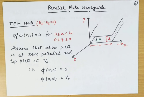
The field linkage for parallel plates is depicted in figure 1 below :
When an electric field links between two conductors, there will be a path of flow of charges or current creating closed loops all around the direction of propagation of the wave. This attribute of propagating all throughout the direction ensures a total transverse electric and transverse magnetic field. That is, the field will propagate only in the electric and magnetic field that run all throughout their conductors. If the field flows through the electric and magnetic field, the field will be in one direction. For a parallel plates waveguide, the spacing between the plates is only 10 cm. The field electric will flow all throughout the conductors and the components are mainly perpendicular to the conductors but there will be longitudinal components known to be EVY. The field for the electric is shown in figure 1. So there will be no TEM mode for the parallel plate waveguides.
In a coaxial cable, the electric field line will run all throughout from one conductor 2 to conductor 1 as shown in figure 2 below. There will be no closed loops enclosing the point of propagation. A typical coaxial, in this case, is RG-6 coaxial cable that is used for cable television with an impedance of 75 ohms. The electric field all through the transverse also the material making the conductor such that the transmission is purely through a transverse electric and magnetic field wave guide. Longitudinal fields are not there in this wave guide. So it is suit for transmitting high definition signals. The field is purely transverse allowing for long distance signal without signal distortion. The signal will travel up to 5 km with no repeaters. In actual coaxial there will always be a solid foam dielectric between the inner 1 and the outer 2 making up a concentric transmission line.
Since parallel plate waveguides cannot form an appropriate electric field linkage, the medium is associated with the absence of TEM mode and the presence of TE and TM modes, which include longitudinal field components. Due to the presence of the longitudinal components, phase shifts and polarization mismatch cannot be avoided. As a result, wave guide efficiency will be poor and also the error of data transmission will be high.
Engineering accountabilities
Given the inefficiencies associated with parallel planar waveguides, engineers have to design alternative routes or identify feasible substitute wave guide types. For customers who require high precision and minimum signal distortions, parallel planar waveguides can be designed in a different way, or other types of waveguides can be utilized. In my personal opinion, an engineer has to assess the linkages that will occur with parallel plates, and then to decide whether the dielectric components of the waveguide can be modified/provided in another way, or are to be replaced by an alternative waveguide. For high frequencies, the waveguide can consider the use of a hollow metallic variety to ensure a good phase link of the waveguide. Engineers can also opt for the optical fibers, which have higher dielectric properties that will modify the field appropriately. The use of optical fibers is practicably different from what the regular customers could attempt given that they are expensive, and the customers may not be able to bear the cost.
Magnetic Field Configuration
Every waveguide has a specific configuration for the magnetic field, which, ultimately, determines which modes of propagation it can be used for. For the TEM mode, the truly crucial factor is that the magnetic field should be purely transverse. It means that the field’s direction should not have any component oriented along the waveguide’s direction, and it should be aligned perfectly to form a circuit around the direction where the electric field is transverse to it. This configuration is important for applications where electromagnetic interference is undesired, such as applications of precision medical imaging. Even slight distortion of a magnetic field in an MRI machine will lead to significant degradation in the quality of images due to inability to bring magnetic fields into the correct configuration.
Parallel planar waveguides that consist of flat conductors make it impossible. The nature of the flat plates is such that the magnetic field line will necessarily flow parallel to the sides of the parallel planes between them. As such, there will always be a longitudinal component to the magnetic field which is undesirable as inconsistent with TEM mode. This makes parallel planar waveguides unsuitable for medical imaging instruments such as MRI where magnetic fields should be perfectly uniform. In practice, coaxial cables or specially designed waveguides will be employed in view of their ability to satisfy the requirement of transverse magnetic fields.
The corresponding requirements to the such magnetic field are such that the parameters of the field should change at no more than a few parts per million across an MRI machine scanning volume. This corresponds to less than 0.0002% fluctuations over an area of fifty centimeters. Such perfect uniformity is required to ensure that magnetic fields do not introduce any errors or artifacts in the images produced.
As applications rely more and more on the high precision and uniformly constant transmission of high-frequency signals, this requirement turns in a significant limitation. Specifically, it is the case for its applications in radar equipment and satellite communications where maintaining the integrity and phase constancy of a signal sent at high frequencies is of utmost importance. While there are other methods of sending electromagnetic radiation at lower frequencies such as through fiber-optic cables or coaxial conductors for radar applications, they do not allow for signal to be transmitted and received at such long distances. The problem of the longitudinal magnetic field is intrinsic to parallel planar waveguides, and engineers will thus either have to design separate waveguides. This will have significant cost implications, as the resulting waveguide will necessarily include some additional parts that might be costly or will require precise engineering to properly perform their function.
Energy Transport Mechanism
The energy transport mechanism in waveguides to a large extent dictates which types of electromagnetic wave propagation are possible. In order for TEM mode to exist, the energy, which consists of both electric and magnetic fields, has to be transported in such a way that neither of these fields possesses a longitudinal component. The existence of this mechanism is crucial to ensuring that modern communication systems, which are heavily dependent on the propagation of broadband internet and other signals over long distances, are as efficient as possible and do not incur signal losses.
In parallel planar waveguides, the transport of electromagnetic energy necessarily results in either electric or magnetic field traveling in the direction of propagation because the structure necessitates it. Because of this construction, the existence of such waveguide is conditional on the implementation of TE and TM modes, where electric and magnetic field, respectively, have the component of longitudinal energy transport.
For a practical application in TV digital broadcasting system that allows for a range of 470-862 MHz, which is terrestrial broadcasting mean, the inability to transport only transverse energy is impractical. Because of these limitations, distance-dependent phase shift and signal loss are inevitable when either TE or TM mode is utilized for broadcasting. When the dimensions of a theoretical waveguide are 50 centimeters in width and 25 centimeters in height, the loss of broadband 470-862 MHz in TE mode is 0.1 – 0.5 dB/meter depending on the particular frequency. Unlike this instance, in coaxial systems, TEM mode can be transported without these additional losses, which rarely exceed 0.05 dB/meter for the same range of conditions. As such, in any implementation, while equally constrained by the physical conditions, engineers are forced to deal with additional losses which can be addressed at the beginning of the design process by selecting a different type of waveguide like a coaxial one.