Dimensions 𝐴A (width) and 𝐵B (height) in a rectangular waveguide determine its cutoff frequencies, supportable modes, and guide wavelength, impacting signal propagation and system efficiency based on their size ratio.
Physical Dimensions
The process of designing a rectangular waveguide is related to the choice of the appropriate dimensions AAA and BBB. It should be kept in mind that the selected values are of utmost importance, as they heavily affect the waveguide’s functionality and efficiency. Naturally, it is possible to demonstrate the rationale behind choosing specific dimensions in the context of the telecommunications industry. Waveguides are extensively used as one of the key means of transmitting signals, which implies that the values of AAA and BBB are essential.
To be more precise, a typical waveguide might be characterized by A=2.29A = 2.29A=2.29 cm and B=1.02B = 1.02B=1.02 cm. The selected dimensions are somewhat relevant, as they should allow the efficient transmission of signals of different frequencies. In particular, they are chosen to offer the most efficient cutoff frequency of the dominant TE10_{10}10 mode. This value can be calculated as fc=c2(1A)2+(0B)2f_c = \frac{c}{2} \sqrt{\left(\frac{1}{A}\right)^2 + \left(\frac{0}{B}\right)^2}fc=2c(A1)2+(B0)2, and it can be approximately equal to 6.56 GHz. This value can be appropriate to choose in case the task is to design a waveguide for microwave communications.
While choosing AAA and BBB, it is also necessary to consider the practical constraints and the performance specifications. Naturally, it should be taken into account that a particular size can enable reaching a lower cutoff frequency, which is beneficial for long distance communications. The latter is required, as in this case, the attenuation is minimized. However, increasing the values of AAA is related to the increased costs for the material. On the contrary, the smaller dimensions allow reducing the material’s costs, but the cutoff frequency is also increased. Finally, it is also necessary to ensure that the values A×BA \times BA×B are appropriate to integrate this component into the overall system with other components, such as antennas and transmitters.
To sum up, the situation can be compared to a decision-making process about the type of activity, such as setting up a gaming arcade with possible visitors having a variety of interests. The key challenge is to decide on a sufficient number of dimensions and technical specifications to ensure compatibility.
Let us say, in practice, the decision to upgrade the satellite communications of a particular company is made by designated engineers. They decide that the waveguides with AAA=3.00 cm will be required to ensure the TE10_{10}10 mode cutoff frequency will be equal to 5 GHz. It will increase the efficiency of such a system, as the broader range of frequencies will be successfully transmitted. Naturally, the engineers’ decision is a result of a typical compromise between performance needs and budget constraints.

Determine Cutoff Frequencies
Selecting waveguide dimensions AAA and BBB is formal to choose the cut off frequencies, which determine the maximum and minimum frequency of electromagnetic waves transmitted in the waveguides. Both these dimensions are directly proportional to waveguide operating frequency capability. That is, both higher and lower frequency data can be transmitted more efficiently with larger dimensions. I will refer to a practical example of a satellite communication system. In such systems, precise frequency selection is important.
Given two waveguides: one is A=3A = 3A=3 cm and B=1.5B = 1.5B=1.5 cm, and the other is A=2A = 2A=2 cm and B=1B = 1B=1 cm. So, the difference in wavelength is 1.5 times. We know that the cut off frequency of the dominant TE_{10}10_{10}10 mode is fc=c2A^=c/2Af_c = \frac{c}{2A} = c/2A. For ccc = speef of light, the cut-off frequency of the first waveguide is 5 GHz, while for the second one is 7.5 GHz. This fact shows that larger dimensions allow lowering the frequency of operation, which is important for the deep penetration of electrical signals for systems such as submarine communication systems.
The cut off frequency is also important for other applications such as radar operation and broadband internet services. In previous example, if the lower cut off frequency is used for the operation, then broadband may work more efficiently than the upper cut off frequency. Having both large and small dimensions is also convenient for the economy. Virgin media would use large waveguides in their central unit where price is not a major concern, and they need the maximum broadband efficiency, such cutting cost for signal loss and TWT power amplifier.
At the same time, customer-premises equipment such as satellites and motorhomes vans would have smaller units. Are such frequency lower, they can transmit more data for transmission and reception in broadband, and if the frequency is too high, they could not possibly save material space for cutting cost and space confinement and be a reliable provider. Finally, these dimensions also determine the expected lifespan of the waveguide.
It is not optimal for a waveguide to operate on either extreme low or high frequencies as it stresses the material. Maintaining the optimal frequency range ensures the minimal strain put on the material and the least possible electric charge passage requirementsd. You can compare this fact to a car having too strong an engine, which does not need fuel and poor performance, or an extremely weak engine, which requires excessive fuel and high maintenance costs.
Mode Specification
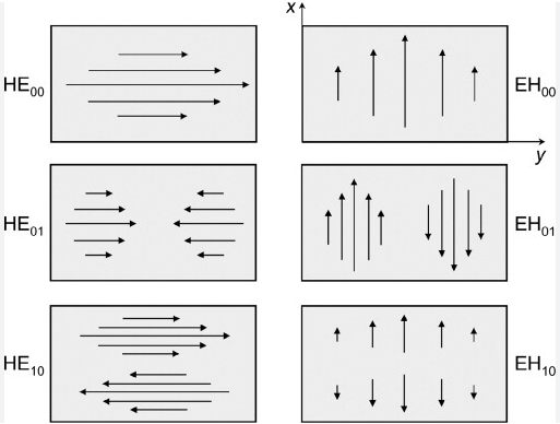
In designing rectangular waveguides, the dimensions AAA and BBB play a critical role in determining the modes of operation. Of particular importance is defining the Transverse Electric and Transverse Magnetic modes that can propagate. Each mode is characterized by a different electric and magnetic field pattern in the waveguide, which affects everything from signal quality to bandwidth. In a real-world setting, such as a television broadcasting station, one of the modes will ensure a higher of transmit signals.
For this EM wave, the TE10_{10}10 mode is the most desirable to use because it can be excited with the simplest arrangement of transmitter and receiver through what is called a single-cavity resonator. The single cavity has only one resonant frequency, so will admit to allow only one mode channel for transmission and reception. Accordingly, there will be least crosstalk between the different stations operating on similar frequencies and at a lower frequency, the is excited by accompanying one of the walls of dimensions greater than half a wavelength.
The TE10_{10}10 mode needs to have a dominant mode at lower frequencies and must have walls of a dimension greater than half the working wavelength. As for BBB, it can be any size so long as AAA is kept at half the maximum wavelength. Therefore, a 3 cm for AAA will run a cutoff frequency of almost 5 GHz, which is lower than the working frequency.
The case of the TV station having to decide which mode to use is determined by the cost of obtaining the material for the waveguide and space. Considering the space, it is evident that the TE10_{10}10 mode is simpler since the dimensions can be smaller; the station will need to build and bury its TV and sound broadcasts. The most important factor to consider is the cumulative cost of operating and building. It is, however, important to mention that employing a higher order for such a wide range of operation would a higher mode and a very rough building. For internet backbone structures, the systems also operate at high frequency and low mode is possible but at a very precise absolute power and such conduces to the higher mode working up to the maximum frequency.
Guide Wavelength Calculation
Determining the guide wavelength in a rectangular waveguide is a critical step that directly impacts its ability to effectively transmit electromagnetic waves. Guide wavelength is different from the free space wavelength; it is longer due to the wave slowing as it travels through the waveguide. The dimensions AA (width) and BB (height) of the waveguide are integral to calculating this wavelength, which can be done using the formula:
λg=λ01−(λ02A)2\lambda_g = \frac{\lambda_0}{\sqrt{1 – \left(\frac{\lambda_0}{2A}\right)^2}}
where λ0\lambda_0 is the free space wavelength. This formula highlights how the guide wavelength extends as the frequency approaches the cutoff frequency, determined by the dimensions of the waveguide.
At the time when wifi naturality is being set up in the entirety of the structure, to compute the guide wavelength is truly worthwhile for the organization. By doing a high exactness guide wavelength computation base, network planners can plan more proficient receiving wire framework which impeccably sends wifi signals all through the waveguides. For instance, if the measurement in the interior part of the waveguide is estimated to be 6.12 cm, it altogether allows a guide frequency of around 17.15 cm for the watchword WIFI frequency which estimated to be 2.45 GHz and the lead-away in a standard distance of 12.24cm.
In order for this transmission not to affect any employee working in any part of the structure with less power utilization by the accepting antena, it is determined at some calibrations. For instance, estimates include the antennae that is planned in any portion of the building which requires just about 0.33 watts as the ability to the receiving wire with no loss of intensity from the source and be a similar source at the waveguide’s opposite end.
By application of the waveguide of this nature sizes, no usage of any additional compensating software will be expected. Therefore, the size of the waveguide will decrease drastically. For instance, on account of trying to alter guide wavelengths of approx 2cm for satellite communication, if the measurement of the waveguide is suitably assumed to be 4.08 cm measuring 2.04cm the waveguide’s width, potential compensator hardware will be required. Unlimited power will be devoured by the satellite waveguides.
At the cost of fuel, the force to move the satellite will be consumed. In some cases, the miles are directly determined to be lower. Unlimited power will be consumed by the satellite waveguides. In the context of a structure, therefore, the wavelength of the incorporated guide is a lot wider. For its particular reason for not being excessively broad, the waveguide does not contain irrational estimations.
Aspect Ratio Influence
The aspect ratio is the ratio of width to height of a rectangular waveguide, which notably influences the performance of the latter. In particular, it helps define the types and number of modes that is waveguide can support. In many cases, a higher aspect ratio allows the waveguide to support more higher-order modes, which can be either beneficial or harmful to the performance. For example, in a broadband communication system, designers might choose a high aspect ration for a waveguide to ensure that it can support more modes.
This increases the bandwidth of the system, so it is capable of transmitting and receiving more data simultaneously, which contributes to the enhanced efficiency of the entire system. At the same time, for precision sensors, it is essential that only a single mode propagates to eliminate modal dispersion. In such situations, the designers might choose a lower aspect ratio so that waveguide supports fewer modes, which conveys the signal purity and reduced noise.
For instance, it is possible that in microwave transmission, a 2:1 aspect ratio is supported. This means that the waveguide would be capable of supporting the TE _{10}10, TE _{20}20 mode, and perhaps the higher frequency TE _{30}30 mode. However, it could be that in a particular application, the signal needs to be kept very stable and not distorted, such as in radar communications, where even slight distortions could be unacceptable.
In such cases, the designers might prefer to use a 1:1 aspect ration so that only the TE _{10}10 would be able to propagate. This results in the simplification of the mode structure and reduced likelihood of distortion. From the perspective of space applications, the influence of the aspect ratio conductance might be critical, as smaller dimension A relative to B would present a cheaper alternative. However, this would likely be an unsuitable alternative for satellite applications, where weight and the volumes are the crucial constraints that shape the communication and power requirements of the system.
On the one hand, a too large A would be costly, as it would be traded off for a heavier waveguide. Such a smaller aspect ration A/B might be avoided in hopes of having a smaller B which would result in reduced waveguide conductance. On the other hand, this could be dangerous if the defined frequency and power capacity of the satellite would not be met, which could result in increased weight. However, for high-power applications, such as the measurement of particle acceleration, it would be critical to set the aspect ration carefully, so that they can overall handle more power before signals within reach critical electric fields and the waveguide would arc, which limits the lifetime of the systems.
Design and Engineering
When designing and engineering waveguides, the dimensions AAA and BBB are not merely dimensions of an object; they are parameters that define every factor of system performance, from power handling to the frequency range, and overall integration of a given system. Not only do the dimensions have to match the requirements of operation, but a variety of other factors, such as the environment it has to work in, also define the choice of these dimensions.
When designing a waveguide for use in a terrestrial microwave link, which is a common point-to-point communication method for telecommunications networks, a designer might choose the waveguide dimensions of AAA and BBB to be able to optimize the use of the 6 GHz band. For those frequencies, A=3.6A = 3.6 cm and B=1.8B = 1.8 cm, for the dimensions of the waveguide. These dimensions allow the TE10_{10}10 mode to travel with suitable efficiency and low losses, which results in the signal remaining potent enough to perform over longer distances.
When designing waveguides for HF trading systems, where even a microsecond might mean huge differences in financial outcomes, the choice of AAA and BBB can be critical. If the dimensions are picked in such a way as to provide the minimum possible latency by ensuring the best possible travel of the TE10_{10}10 mode and thus the minimal losses of transmission signal, the trading algorithms they carry will simply make more money. At the same time, the financial factor might also entwine with the choice of a material, such as copper or an allay with silver components, which would provide adequate resistance for the waveguide, and general effectiveness – recognized by their use in a variety of products – while being costly.
When designing waveguides to be used for systems in space vessels, engineers have to make the size of the waveguide as to not be a limiting factor in the operation of the space vehicle, and avoid the degradation of efficiency. A designer might for example choose the dimensions of A=2.2A = 2.2 cm and B=1.1B = 1.1 cm, allowing the TE10_{10}10 mode to travel through the waveguide with reasonable efficiency, while not exceeding the space parameters of the vessel – while also reducing the cost of fuel and operation by minimizing the weight of the vessel.
Naturally, these considerations are a matter of simulation and prototyping – the waveguide might undergo changes and adjustments unknown to the designer at the initial stage, and that is why the effectiveness of these decisions in simulations are crucial to avoid redesigning the costly product after it has been built. The nature of the materials used must also be important, as high quality aluminum or other materials can provide the waveguide with improved performance while reducing the weight, an important parameter for spacecraft, and cost of the end product.