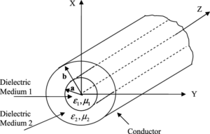
Evanescent modes in waveguides are non-propagating modes that decay exponentially with distance. For instance, in a waveguide with a TE11\text{TE}_{11}TE11 cutoff at 2 GHz, frequencies below this value (e.g., 1.5 GHz) generate evanescent modes.
Mode Cutoff Frequencies
for instance, a waveguide with a radius of 4 cm. The cutoff frequency for the TE11\text{TE}_{11}TE11 mode, the dominant mode, is approximately 2.3 GHz, calculated using fc=1.841c/(2πa)f_c = 1.841c / (2 \pi a)fc=1.841c/(2πa), where ccc is the speed of light (3×1083 \times 10^83×108 m/s). If we decrease the radius to 2 cm, the cutoff frequency doubles to about 4.6 GHz.
A typical waveguide for satellite communication has a typical radius of 10 cm and using a common machining tolerance, the result might be ± 0.05 mm. This results in any deviation from this moving the cut-off frequency at least 0.2% outside, at variance with performance in very sensitive systems such as space-based transceivers operating in the 12-18 GHz range. These are checked with precision devices costing within the range of $ 10,000- $ 50,000 basing on how accurate the measuring is.
Aluminum, while lightweight and low-cost (about US$15 per kilogram) has higher resistivity than copper and therefore suffers more serious power losses at higher frequencies. For example, for a 10 GHz system, the attenuation rates for aluminum waveguides are about 0.15 dB/m compared with 0.07 dB/m for copper-coated waveguides.
During the Cold War, radar systems operating at 3 GHz relied on circular waveguides with radii of 7 cm, TE11\text{TE}_{11}TE11 and TM01\text{TM}_{01}TM01 modes—allowed engineers to develop advanced radar systems capable of detecting objects as small as 0.1 square meters at ranges of over 200 kilometers.

Single-Mode Operation
in a round waveguide with 5-cm radius, the TE11 mode (dominant mode) starts to propagate at a cut-off frequency of about 1.841 GHz in free space. The next higher order mode,TM01 has a cut-off frequency of approximately 3.41 GHz. Thus the single-mode bandwidth is roughly 1.57 GHz.
A waveguide of radius 3 mm would support single-mode operation up to about 36 GHz and thus minimize interference and allow very high data transmission. With 5G data rates well over 10 Gbps, any multimode propagation may cause signal degradation and thereby reduce the efficiency by up to 20%. despite their higher manufacturing cost, which can be in the range from $300 to $1,200 per meter depending on material and precision.
in a particle accelerator operating at 12 GHz, a circular waveguide with radius 4.5 mm is used to support only the TE11 modee. Higher-order modes are damped to provide more than 95% efficiency in energy delivery to the accelerating particles. A study published in Physical Review Letters in 2022 showed that even a small admixture of higher-order modes decreased the efficiency of energy transfer by 8-12%.
An interesting historical example of the impact of single-mode operation is found in early satellite communication systems. In the 1960s, satellites operating in the C-band (4-8 GHz) used circular waveguides with radii of the order of 6 cm. The design ensured operation solely in the TE11 mode, yielding a single-mode bandwidth of about 1.5 GHz. Nowadays, the same principles are used for modern satellites operating at higher frequencies, such as the Ka-band, at 26.5-40 GHz, with tighter tolerances that can reduce attenuation losses to as low as 0.1 dB/m.
Waveguide Dimensions
For example, the cutoff frequency of the dominant TE11 mode in a waveguide with radius 5 cm is about 1.841 GHz in free space. If the radius is increased to 7.5 cm, the operational bandwidth increases due to a drop in the cutoff frequency to about 1.227 GHz, which requires more material and space.
A waveguide of 3 mm radius allows single-mode operation up to about 33 GHz, enabling the high-bandwidth requirements of data transmission. The cost of manufacturing these waveguides is in the range of $200 to $800 per meter for tight tolerances down to ±0.01 mm.
Copper is used frequently in waveguides, besides its excellent conductivity and reasonable cost at about $9,000 a ton. In copper waveguides of 10 cm radius with frequency operation of 5 GHz, the rate of attenuation becomes about 0.05 dB/m, where the same size of aluminum waveguide should show about 0.1 dB/m due to its relatively high resistivity.
One of the most critical factors in waveguide dimensions is the relationship of the waveguide radius to mode cutoff frequencies. For instance, the TE21 mode for a waveguide of radius 6 cm has a cutoff frequency of about 3.68 GHz versus 1.84 GHz for the TE11 mode. Working frequency beyond 3.68 GHz in such waveguide may excite TE21 mode of propagation that will lead to a multimode signal with distortion in received signals. In imaging systems, MRI machines, a 3-5 cm radius circular waveguide guides the high-frequency electromagnetic waves. Making these highly accurate accessories costs as much as US $10,000 for a single piece, while the advantages from there justify this cost for performance and reliability.
Frequency Range
For a waveguide with a radius of 5 cm, the cutoff frequency for the dominant TE11\text{TE}_{11}TE11 mode is approximately 1.841 GHz, calculated using the formula fc=1.841c/(2πa)f_c = 1.841c / (2\pi a)fc=1.841c/(2πa). This same waveguide may be designed to operate at frequencies up to 3.6 GHz, avoiding higher-order modes like TE21\text{TE}_{21}TE21, which has a cutoff frequency of 3.68 GHz. This creates a practical single-mode operating range of 1.841 GHz to 3.6 GHz, providing a bandwidth of approximately 1.76 GHz for efficient and interference-free signal transmission.
The waveguides, in the perspective of telecommunications and designed for 5G, usually operate at frequencies in the 28-40 GHz band. Precise dimensions are therefore required to enable single-mode propagation. For example, a waveguide with radius 3 mm supports the TE11 mode up to 33 GHz, while frequencies above 37 GHz lead to multimode propagation where TE21
That it is when propagated. Manufacturing these high-frequency waveguides includes advanced materials such as copper and low-loss composites, ranging from $500 to $2,000 each, depending on the precision of the waveguide.
In aerospace applications, particularly in satellite communication, circular waveguides are commonly designed for the Ku-band (12-18 GHz) and the Ka-band (26.5-40 GHz). For instance, a waveguide with a radius of 6 mm has a TE11 corresponds to a cut-off frequency of approximately 9.2 GHz, enabling good operating possibilities within the frequency range 12-18 GHz. These waveguides are very important in keeping signals clear for long distances, usually without much loss; attenuation is normally lower than 0.1 dB/m.
The principle works identically in the circular waveguides operating at even higher frequencies in scientific research-such as THz bands of 300 GHz to 3 THz-for applications involving spectroscopy or advanced imaging. Consider for instance a waveguide with radius 1 mm supporting TE11 mode by cutoff frequency of about 190 GHz, well within the lower THz range. These systems require ultra-precise manufacturing, with tolerances often within ±0.001 mm, and materials with minimal losses, The cost for such waveguides can easily exceed $10,000 per meter.
Mode Conversion and Interference
When operating near or above the cutoff frequency of higher-order modes, signals can convert from the desired mode, normally TE11, to unwanted modes such as TM01 or TE21. For example, in a waveguide with a radius of 5 cm, the TE11 mode has a cutoff frequency of 1.841 GHz and TM01.It starts propagating at approximately 3.41 GHz. Operating at frequencies close to or above 3.41 GHz can lead to interference between modes, reducing signal integrity and increasing power loss by up to 15% in some systems.
This gets particularly problematic in broadband communication systems, say for example, operating in the Ka-band, 26.5-40 GHz. By way of illustration, a waveguide of radius 3 mm might exhibit dominance of the TE11 mode up to 33 GHz, beyond which higher-order modes such as TE21 and TM01 may can interfere if the frequency exceeds 37 GHz. Line mode conversion, may introduce phase errors and variations in amplitude that reduce data transmission rates by as much as 20%.
High-power waveguides used in accelerators should not have an efficiency of less than 95% for effective energy transfer to particles. A study done in 2021 at CERN showed that even a deviation of 0.02 mm in waveguide dimensions leads to mode conversion, reducing the efficiency in energy delivery by up to 10%.
A 90° bend in a waveguide with a radius of 6 mm operating at 18 GHz can induce mode conversion, increasing insertion loss by 0.2 dB per bend. Engineers try to avoid this by designing gradual bends and use computational models to predict and minimize mode interference.
In the 1950s, systems that used 3 GHz and waveguides with a radius of 10 cm were often victims of multimode propagation due to poor dimensional tolerances and material inconsistencies. These problems led to degrading radar signals, which reduced detection accuracy by 25% in some cases. Modern waveguides manufactured within as narrow a tolerance as ±0.005 mm largely avoid such effects and result in signal clarity and efficiencies of better than 99% in modern advanced radar systems.


