Optical couplers can split or combine signals, useful in data centers for managing traffic up to 100 Gbps. Splitters, ideal for telecom, distribute a single signal to up to 64 subscribers over 20 km. Directional couplers, used in radar systems, isolate signals and handle several kilowatts of power.
Function
Optical couplers are designed to split or combine optical signals within the fiber optic networks to facilitate effective data traffic management. For example, in a typical data center, a 1×4 optical coupler would split incoming signals from a single fiber onto four different Servers. The devices are capable of splitting optical power onto as much as 32 outputs that makes each output receiving a fraction of the input signal’s power. At that, the fraction’s proportion may vary from 3dB to 6dB per split making these parameters crucial for planning the needs for network amplification.
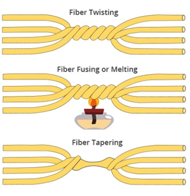
The optical splitters are the subtype of optical couplers capable of splitting a single input signal into multiple output signals with minimal loss. Typically, the splitters are used in applications, such as telecommunications and FTTH systems. Here, a single input optical signal can be split on average into 16 output signals with each connected household receiving an equal share of the signal. The total loss might equal up to 0.2db per split, which makes an PLC contained split an effective solution for broad distribution networks.
Directional couplers are used for signal routing dependently on the signal’s direction of propagation. In particular, one uses the directional couplers in applications where signal direction routing is essential for managing reflection and interference. One may think of a directional coupler as a means of measuring the power of a transmitted radio frequency signal without interrupting the main flow of signals. In this connection, the devices may handle power input in the range of 0.5 to 50 watts dependent on the design and materials used for manufacturing.
Characteristics
Optical couplers are designed to manage the distribution and combination of signals with the needed flexibility to support both split and combined configurations in the needed network or environmental settings. A standard coupler designed for optical applications will typically operate on multiple sensors within a single fiber or set of fibers. For example, an optical coupler might be used to connect to multiple sensors within a single home and automatically transmit signals from the individual sensors to monitor different areas of the home. All signals that are combined with the optical coupler through the home monitoring system will provide an output of power that does not exceed the approximately 10 watt combined power capacity of the coupler.
This will guarantee the integrity of the signal while keeping the 10 watts from splitting throughout the system. In this sense, an optical coupler is one that combines and divides the signals as needed throughout the central processing unit through which it is distributed without loss of signal integrity.. Splitters differ greatly from couplers in that their main function is to split a single optical signal into multiple paths and do not have the capacity to combine signals. They provide the strength of the signal or intensity of the light and divide it into the needed proportions throughout the network where it is in constant and reliable distribution. For example, within a network that employs FTTH architecture, the splitter will be able to accomodate up to 32 individual households through a single fiber.
Each of the 32 networks will receive a roughly equivalent division of the original signal’s power. In higher definition PLC splitters in telecommunications, the amount of loss will typically be less than half a single decibel per output path, which is essential in servicing a powerful yet high quality signal throughout the connected premises. Directional couplers differ from standard optical or other types of couplers in that they are able to direct the flow of signal based on the direction of the propagation of light or if an electric signal is used. This is necessary in situations where the flow of signal must be isolated between different parts of a system or network.
In a network that uses a television broadcasted signal, a standard directional coupler might be used to separate and evenly distribute the needed signal to multiple broadcasters while ensuring that signals received by one will not affect the signal received at another. The loss of insertional to the properties of a directional coupler will typically not exceed 0.1 decibel and the output will vary from low to 50 watts in different applications. In conclusion, all couplers, especially directional ones, serve the purpose of manipulating signal distribution based on the intensity or integrity of the signal.
Usage
Optical couplers
Optical couplers are used in highly versatile network configurations where it is necessary to both split the signal and combine multiple inputs. In general, in a data center such a device may be used to introduce flexibility in the routing of data traffic from the servers to the storage. Thus, if there is an imbalance or failure in one part of the network, the whole network will not be impacted by the malfunction of that one part. Moreover, couplers are generally capable of handling up to 100 Gbps, which is sufficient to allow high-speed data processing of large database entries.
Splitters
Splitters are mainly used in telecommunications, which refers mainly to PONs, or passive optical networks, which are a generally used by providers to offer broadband services. A single splitter can function from 2 or more sides and split the signal to feed multiple endpoints, which increases the capacity of a single device to work with dozens of subscribers, up to 64. As a result, the use of splitters is a highly economical choice for all network providers. The distance of up to 20 km for a single network also indicates the device’s efficiency and the use of high-quality materials in its manufacturing equipment.
Directional couplers
Directional couplers are used in the systems where the signal needs to be directed and the leakage minimized to ensure the efficiency and integrity of the system. Typically, such devices are used in RF applications, such as in the radar, which cannot allow the transmission pulse to spread over to the receiver and interfere with its work. The handling of up to several kilowatts of power also allows these devices to be used in such high-power applications as broadcasting and military communication.