The optimal distance varies, typically ranging from 5 to 20 cm, based on frequency, power, and application specifics.
Understanding the Distance Between Directional Couplers
Factors Affecting the Distance
The distance between directional couplers plays a crucial role in their performance and is influenced by several key factors:
- Frequency Range: Directional couplers designed for lower frequencies may require larger distances between couplers to minimize interference. A coupler operating at 2 GHz might have an optimal distance of 10 cm, whereas one at 5 GHz might perform best at a 5 cm distance.
- Coupling Factor: The strength of the signal that is diverted from the main line to the coupled line is a vital consideration. A higher coupling factor often necessitates adjustments in the physical distance to maintain signal integrity. A coupler with a 30 dB coupling factor may need a distance adjustment of 2 cm more compared to one with a 10 dB factor.
- Power Handling: The ability of a directional coupler to handle power without degrading is directly related to its physical spacing. Couplers intended for high-power applications, those exceeding 100 watts, typically require greater distances between each coupler to dissipate heat effectively and prevent damage.
Calculation Methods for Optimal Distance
To determine the optimal distance between directional couplers, engineers employ several calculation methods:
- Empirical Formulae: Based on experimental data, these formulae provide a starting point for estimating distances. An empirical formula might suggest that the distance (D) in centimeters can be approximated as D = (F / C) * P, where F is the frequency in GHz, C is the coupling factor, and P is the power in watts.
- Simulation Tools: Advanced software simulations allow for precise modeling of directional couplers in various configurations. By inputting parameters such as frequency, coupling factor, and power handling, engineers can visualize the impact of distance on performance metrics like insertion loss and VSWR (Voltage Standing Wave Ratio).
- Prototype Testing: Physical testing of coupler prototypes remains a definitive method for fine-tuning distances. By constructing test setups that allow for adjustable distances, engineers can directly observe the effects on performance and make the necessary adjustments. This hands-on approach often reveals that a coupler designed for a 5 GHz application with a 20 dB coupling factor and 50 watts of power handling performs optimally at a distance of approximately 7 cm, a specific finding that simulations and formulae can approximate but not perfectly predict.
The integration of these methods ensures the accurate determination of the optimal distance between directional couplers, balancing performance with practical considerations such as size and cost. A telecommunications company might find through simulation and testing that reducing the distance between couplers in a new antenna design from 10 cm to 8 cm could enhance signal clarity while only marginally increasing the cost, a worthwhile trade-off for superior customer experience.
Design Considerations for Directional Couplers
In the realm of directional couplers, the selection of materials and fabrication techniques plays a critical role in determining their performance, efficiency, and application suitability. Materials with superior thermal conductivity, such as copper or silver, stand out for high-power applications, directly impacting the coupler’s ability to dissipate heat effectively. Specifically, silver’s higher thermal conductivity allows a directional coupler to handle up to 20% more power compared to one made of copper, making it a preferred choice for scenarios demanding high power handling.
When it comes to fabrication techniques, the precision afforded by methods like lithography is paramount, especially for couplers destined for high-frequency operations. A directional coupler crafted using advanced lithography can boast a Voltage Standing Wave Ratio (VSWR) of less than 1.2:1, a testament to the importance of meticulous fabrication in achieving optimal performance metrics.
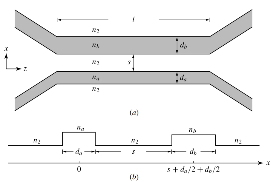
The physical dimensions of directional couplers, such as their length, width, and the spacing between elements, are intrinsically linked to their operational frequency and efficiency. The size of a coupler is inversely proportional to its operational frequency, necessitating smaller couplers for higher frequency applications. A coupler designed for 10 GHz might be merely 3 cm long, significantly shorter than a 30 cm coupler intended for 1 GHz frequencies. This variation not only affects the coupler’s practical applications but also its core performance characteristics like insertion loss and isolation.
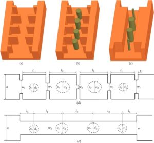
Adjusting the spacing between the coupled lines within a directional coupler is a delicate balance that can significantly affect its coupling level and bandwidth. A minor adjustment in spacing, say from 2 mm to 1.5 mm, could enhance the coupling from 10 dB to 12 dB, showcasing the critical nature of physical dimensions in achieving precise and desired performance outcomes.
The design and construction of directional couplers demand a careful consideration of materials, fabrication techniques, and physical dimensions. The choice of high-conductivity materials, coupled with precision fabrication and meticulous design, can markedly improve the performance and efficiency of directional couplers, making them indispensable tools in modern telecommunications and microwave engineering.
Applications of Directional Couplers in Different Distances
Telecommunications
In the telecommunications industry, directional couplers serve as vital components for signal distribution and monitoring. The optimal distance between couplers is crucial for maintaining signal integrity across various communication channels. In fiber optic networks, couplers with minimal distance can lead to signal overlap and interference, disrupting communication flow. A typical setup might require couplers spaced at least 10 cm apart to ensure clear signal transmission, especially in dense wavelength division multiplexing (DWDM) systems where multiple signals are transmitted simultaneously.
Directional couplers also play a key role in antenna arrays for cellular networks. Adjusting the distance between couplers allows for precise control over signal phasing, enhancing signal reach and reducing dead zones. In a cellular base station, couplers spaced 20 cm apart might optimize signal coverage, improving call quality and data transmission speeds. This spacing is determined by both the operational frequency of the network and the physical geography of the service area.
Microwave Engineering
In microwave engineering, directional couplers are indispensable for measuring the power of microwave signals and for ensuring efficient energy transfer in radar systems, satellite communications, and microwave transmitters. The distance between couplers in these applications is often dictated by the wavelength of the microwave signals. For a system operating at 10 GHz, which corresponds to a wavelength of approximately 3 cm, couplers might be spaced at intervals of roughly 6 cm, half a wavelength, to maximize coupling efficiency without causing unwanted reflections.
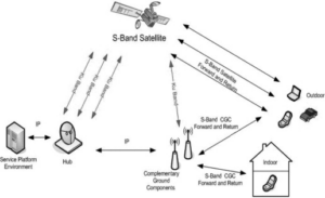
Efficiency in power transfer is paramount in satellite communication systems, where the power budget is tightly constrained. By carefully selecting the distance between directional couplers, engineers can minimize power loss, ensuring that the maximum amount of signal reaches the satellite’s transponders. A satellite system designed for high-efficiency transmission might employ couplers with a spacing that reduces insertion loss to less than 0.1 dB, significantly conserving power in the process.
Directional couplers, by virtue of their design and the strategic consideration of their placement, become crucial elements in the architecture of telecommunications and microwave engineering systems. Their ability to precisely control signal direction and power based on their spacing makes them invaluable in optimizing the performance and efficiency of these systems. Whether improving signal clarity in a fiber optic network or ensuring efficient power use in a satellite communication system, the application of directional couplers is a testament to their versatility and critical role in modern communications technology.